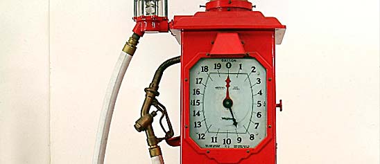
Energy & Power

The Museum's collections on energy and power illuminate the role of fire, steam, wind, water, electricity, and the atom in the nation's history. The artifacts include wood-burning stoves, water turbines, and windmills, as well as steam, gas, and diesel engines. Oil-exploration and coal-mining equipment form part of these collections, along with a computer that controlled a power plant and even bubble chambers—a tool of physicists to study protons, electrons, and other charged particles.

A special strength of the collections lies in objects related to the history of electrical power, including generators, batteries, cables, transformers, and early photovoltaic cells. A group of Thomas Edison's earliest light bulbs are a precious treasure. Hundreds of other objects represent the innumerable uses of electricity, from streetlights and railway signals to microwave ovens and satellite equipment.

Original switch key by which current was turned on lamps in the building. #499 and 451 Water Street, New York City, on the evening of January 15, 1881. A wooden pivot switch mounted on a wooden base. Four binding posts.
Description (Brief)
Original switch key by which current was turned on lamps in the building. #499 and 451 Water Street, New York City, on the evening of January 15, 1881. A wooden pivot switch mounted on a wooden base. Four binding posts. Used in the Hinds-Ketchum printing plant as part of the first commercial installation of the Edison lighting system.
Date made
1881
ID Number
EM.180942
catalog number
180942
accession number
24315
This object may be the first laser. It was made by Theodore Maiman and his assistant Irnee D'Haenens at Hughes Aircraft Company in May 1960.In 1959 Maiman attended a technical conference on the subject of lasers.
Description
This object may be the first laser. It was made by Theodore Maiman and his assistant Irnee D'Haenens at Hughes Aircraft Company in May 1960.
In 1959 Maiman attended a technical conference on the subject of lasers. Maiman heard several speakers state that ruby was unsuitable for a laser but grew troubled by some of the numbers they cited. When he returned to his lab at Hughes he began experimenting. By May 1960 he and D'Haenens constructed several small metal cylinders. Each contained a photographer's spiral-shaped, xenon flashlamp that surrounded a small cylindrical crystal of synthetic ruby. When they fired the flashlamp, the burst of light stimulated the ruby crystal to emit a tightly focused pulse of light--the first operating laser.
Hughes Aircraft donated this and several other pieces of Maiman's apparatus to the Smithsonian in 1970. The crystal mounted inside this unit is from a 1961 experiment. While the donation records indicate that this is the first laser, Maiman wrote that he received the first laser as a gift when he left the company in April 1961. Several experimental models were made during the research, a common practice. So we may never know which unit actually generated the first laser light.
Location
Currently not on view
Date made
1960
associated date
1960
maker
Maiman, Theodore H.
Hughes Aircraft Company
ID Number
EM.330050
accession number
288813
catalog number
330050
The development of practical fluorescent lamps took decades, and many researchers contributed.
Description
The development of practical fluorescent lamps took decades, and many researchers contributed. Julius Plucker and Heinrich Geissler made glowing glass tubes in the 1850s, about the time George Stokes discovered that invisible ultraviolet light made some materials glow or "fluoresce." Alexandre Edmond Becquerel put fluorescent materials in a Geissler tube in 1859, though his tubes did not last long. Carbon dioxide-filled tubes by D. McFarlan Moore and mercury vapor tubes by Peter Cooper Hewitt around 1900 gave practical experience with gas-filled, discharge lamps and inspired the neon tubes of Georges Claude.
In 1926 Friedrich Meyer, Hans Spanner, and Edmund Germer of Germany patented an enclosed glass tube containing mercury vapor, electrodes at either end, and a coating of fluorescent powders called phosphors. This incorporated all of the features we see in modern fluorescent tubes, but their employer did not pursue development. William Enfield of General Electric saw phosphor-coated neon tubes in France in the early 1930s, and heard that European researchers were developing a fluorescent lamp. An especially urgent 1934 letter from a consultant, Nobel-laureate Arthur Compton, coming on the heels of European breakthroughs in low-pressure sodium and high-pressure mercury lamps, spurred both GE and its licensee Westinghouse into combined action.
Enfield created a team led by George Inman, and by the end of 1934 they made several working fluorescent lamps, including the one seen here. To save time, the team adopted the design of an existing tubular incandescent lamp in order to make use of available production equipment and lamp parts. Speed was important. In addition to European competitors, American companies like Sylvania were also working on fluorescents. A second GE group under Philip Pritchard worked on production equipment. Other GE groups in Schenectady and in Ft. Wayne assisted in developing ballasts and resolving problems of circuit design.
In 1936 GE and Westinghouse demonstrated the new lamp to the U.S. Navy (that lamp is in the Smithsonian's collection). The public finally saw fluorescent lamps in 1939 at both the New York World's Fair and the Golden Gate Exposition in San Francisco. These early lamps gave twice the energy efficiency of the best incandescent designs. Production of fluorescent lamps, slow at first, soon soared as millions were installed in factories making equipment for the American military during World War 2.
Lamp characteristics: Double-ended without bases. Flat presses with an exhaust tip near one press. A tungsten electrode, CC-6 configuration coated with emitter, is set at either end. A mercury pellet is loose inside the lamp. The clear T-7 glass envelope has a phosphor coating covering about 3 inches (8 cm) of the lamp near the center.
date made
ca. 1934
Date made
ca 1934
manufacturer
General Electric
ID Number
1997.0388.41
accession number
1997.0388
catalog number
1997.0388.41
This is an experimental device made by Theodore Maiman at Hughes Aircraft in late 1959 or early 1960 as part of the series of experiments leading up to the demonstration of the first laser in May 1960.
Description
This is an experimental device made by Theodore Maiman at Hughes Aircraft in late 1959 or early 1960 as part of the series of experiments leading up to the demonstration of the first laser in May 1960. This object features a cube-shaped ruby crystal mounted at one end of a microwave wave-guide. Maiman sought to test the response of the synthetic ruby crystal to microwave stimulation. Other researchers claimed that ruby would be a poor material to use in a laser. Maiman thought otherwise.
After Charles Townes invented the microwave-emitting maser in 1954, researchers began trying to move to the higher energy levels of infrared and visible light. They referred to such devices as "optical masers," and only later did people adopt Gordon Gould's term, "laser." This experimental piece clearly shows the influence of microwave technology. The metal tube is not a stand but rather a hollow guide that channels microwaves to the ruby crystal. The results of this and other experiments led Maiman to ultimately choose a cylinder of ruby rather than a cube for his laser.
Location
Currently not on view
date made
1959
associated date
1960
associated user
unknown
associated institution
Hughes Research Laboratories
maker
Maiman, Theodore H.
Hughes Aircraft Company
ID Number
EM.330052
accession number
288813
catalog number
330052
Experimental LEAP (Linear Exhaust And Processing) tungsten halogen lamp for a production method that used a laser.Currently not on view
Description (Brief)
Experimental LEAP (Linear Exhaust And Processing) tungsten halogen lamp for a production method that used a laser.
Location
Currently not on view
date made
1972
maker
General Electric Lighting Company
ID Number
1996.0082.04
catalog number
1996.0082.04
accession number
1996.0082
Production model SLS20 "Earth Light" compact fluorescent lamp to replace a 75 watt incandescent lamp.Currently not on view
Description (Brief)
Production model SLS20 "Earth Light" compact fluorescent lamp to replace a 75 watt incandescent lamp.
Location
Currently not on view
date made
ca 1993
maker
Philips Lighting Co.
ID Number
1996.0357.02
accession number
1996.0357
catalog number
1996.0357.02
Date made
1882
date made
1887
associated person
Edison, Thomas Alva
maker
Bergmann & Co.
ID Number
EM.181754
catalog number
181754
accession number
33261
The discovery of nuclear fission in uranium, announced in 1939, allowed physicists to advance with confidence in the project of creating "trans-uranic" elements - artificial ones that would lie in the periodic table beyond uranium, the last and heaviest nucleus known in nature.
Description
The discovery of nuclear fission in uranium, announced in 1939, allowed physicists to advance with confidence in the project of creating "trans-uranic" elements - artificial ones that would lie in the periodic table beyond uranium, the last and heaviest nucleus known in nature. The technique was simply to bombard uranium with neutrons. Some of the uranium nuclei would undergo fission, newly understood phenomenon, and split violently into two pieces. In other cases, however, a uranium-238 nucleus (atomic number 92) would quietly absorb a neutron, becoming a nucleus of uranium-239, which in turn would soon give off a beta-particle and become what is now called neptunium-239 (atomic number 93). After another beta decay it would become Element 94 (now plutonium-239)
By the end of 1940, theoretical physicists had predicted that this last substance, like uranium, would undergo fission, and therefore might be used to make a nuclear reactor or bomb. Enrico Fermi asked Emilio Segre to use the powerful new 60-inch cyclotron at the University of California at Berkeley to bombard uranium with slow neutrons and create enough plutonium-239 to test it for fission. Segre teamed up with Glenn T. Seaborg, Joseph W. Kennedy, and Arthur C. Wahl in January 1941 and set to work.
They carried out the initial bombardment on March 3-6, then, using careful chemical techniques, isolated the tiny amount (half a microgram) of plutonium generated. They put it on a platinum disc, called "Sample A," and on March 28 bombarded it with slow neutrons to test for fission. As expected, it proved to be fissionable - even more than U-235. To allow for more accurate measurements, they purified Sample A and deposited it on another platinum disc, forming the "Sample B" here preserved. Measurements taken with it were reported in a paper submitted to the Physical Review on May 29, 1941, but kept secret until 1946. (The card in the lid of the box bears notes from a couple of months later.)
After the summer of 1941, this particular sample was put away and almost forgotten, but the research that began with it took off in a big way. Crash programs for the production and purification of plutonium began at Berkeley and Chicago, reactors to make plutonium were built at Hanford, Washington, and by 1945 the Manhattan Project had designed and built a plutonium atomic bomb. The first one was tested on July 16, 1945 in the world's first nuclear explosion, and the next was used in earnest over Nagasaki. (The Hiroshima bomb used U-235.)
Why is our plutonium sample in a cigar box? G.N. Lewis, a Berkeley chemist, was a great cigar smoker, and Seaborg, his assistant, made it a habit to grab his boxes as they became empty, to use for storing things. In this case, it was no doubt important to keep the plutonium undisturbed and uncontaminated, on the one hand, but also, on the other hand, to make it possible for its weak radiations to pass directly into instruments - not through the wall of some closed container. Such considerations, combined probably with an awareness of the historic importance of the sample, brought about the storage arrangement we see.
Location
Currently not on view
Date made
1941-05-21
Associated Date
1941-05-29
referenced
Segre, Emilio
Seaborg, Glenn T.
Kennedy, Joseph W.
Wahl, Arthur C.
Lewis, G. N.
University of California, Berkeley
maker
Segre, Emilio
Seaborg, Glenn
ID Number
EM.N-09384
catalog number
N-09384
accession number
272669
Mary Nimmo Moran chose The Goose Pond, Easthampton as her diploma work when the recently formed Royal Society of Painter-Etchers in London elected her a Fellow in 1881, the only woman among the sixty-five original Fellows.
Description
Mary Nimmo Moran chose The Goose Pond, Easthampton as her diploma work when the recently formed Royal Society of Painter-Etchers in London elected her a Fellow in 1881, the only woman among the sixty-five original Fellows. When she exhibited four etchings in the Society’s show, the New York Herald commented on a review in a London paper, ‘“Mrs. Moran’s work is so masculine [sic] that the Daily News critic takes it for that of a man.”’ Her vigorous etching style has been frequently noted along with her preference for working outdoors directly on a prepared plate, before the subject.
The print shows a pond, now known as Town Pond, and Gardiner’s Mill, which still stands in the town of East Hampton, where the Morans spent many summers. Landscape and in particular the landscape around East Hampton was the subject of many of Mary Nimmo Moran’s etchings.
Location
Currently not on view
Date made
1881
graphic artist
Moran, Mary Nimmo
ID Number
GA.14566
catalog number
14566
accession number
94830
Background on Nier Mass Spectrograph; object id no. 1990.0446.01; catalog no. N-09567This object consists of the following three components: ion source with oven and acceleration electrode; semicircular glass vacuum chamber; ion collector with two plates.
Description
Background on Nier Mass Spectrograph; object id no. 1990.0446.01; catalog no. N-09567
This object consists of the following three components: ion source with oven and acceleration electrode; semicircular glass vacuum chamber; ion collector with two plates. The original device included an electromagnet, which is not part of this accession.
In 1939, as political tensions in Europe increased, American physicists learned of an astonishing discovery: the nucleus of the uranium atom can be split, causing the release of an immense amount of energy. Given the prospects of war, the discovery was just as worrying as it was intellectually exciting. Could the Germans use it to develop an atomic bomb?
The Americans realized that they had to determine whether a bomb was physically possible. Uranium consists mostly of the isotope U-238, with less than 1% of U-235. Theoreticians predicted that it was the nuclei of the rare U-235 isotope that undergo fission, the U-238 being inactive. To test this prediction, it was necessary to separate the two isotopes, but it would be difficult to do this since they are chemically identical.
Alfred Nier, a young physicist at the University of Minnesota, was one of the few people in the world with the expertise to carry out the separation. He used a physical technique that took advantage of the small difference in mass of the two isotopes. To separate and collect small quantities of them, he employed a mass spectrometer technique that he first developed starting in about 1937 for measurement of relative abundance of isotopes throughout the periodic table. (The basic principles of the mass spectrometer are described below.)
As a measure of the great importance of his work, in October 1939, Nier received a letter from eminent physicist Enrico Fermi, then at Columbia University, expressing great interest in whether, and how, the separation was progressing. Motivated by such urging, by late February 1940, Nier was able to produce two tiny samples of separated U-235 and U-238, which he provided to his collaborators at Columbia University, a team headed by John R. Dunning of Columbia. The Dunning team was using the cyclotron at the University in numerous studies to follow up on the news from Europe the year before on the fission of the uranium atom. In March 1940, with the samples provided by Nier, the team used neutrons produced by a proton beam from the cyclotron to show that it was the comparatively rare uranium-235 isotope that was the most readily fissile component, and not the abundant uranium-238.
The fission prediction was verified. The Nier-Dunning group remarked, "These experiments emphasize the importance of uranium isotope separation on a larger scale for the investigation of chain reaction possibilities in uranium" (reference: A.O. Nier et. al., Phys. Rev. 57, 546 (1940)). This proof that U-235 was the fissile uranium isotope opened the way to the intense U.S. efforts under the Manhattan Project to develop an atomic bomb. (For details, see Nier’s reminiscences of mass spectrometry and The Manhattan Project at: http://pubs.acs.org/doi/pdf/10.1021/ed066p385).
The Dunning cyclotron is also in the Modern Physics Collection (object id no. 1978.1074.01; catalog no. N-09130), and it will be presented on the SI collections website in 2015. (Search for “Dunning Cyclotron” at http://collections.si.edu/search/)
The Nier mass spectrometer used to collect samples of U-235 and U-238 (object id no. 1990.0446.01)
Nier designed an apparatus based on the principle of the mass spectrometer, an instrument that he had been using to measure isotopic abundance ratios throughout the entire periodic table. As in most mass spectrometers of the time, his apparatus produced positive ions by the controlled bombardment of a gas (UBr˅4, generated in a tiny oven) by an electron beam. The ions were drawn from the ionizing region and moved into an analyzer, which used an electromagnet for the separation of the various masses. Usually, the ion currents of the separated masses were measured by means of an electrometer tube amplifier, but in this case the ions simply accumulated on two small metal plates set at the appropriate positions. Nier’s mass spectrometer required that the ions move in a semicircular path in a uniform magnetic field. The mass analyzer tube was accordingly mounted between the poles of an electromagnet that weighed two tons, and required a 5 kW generator with a stabilized output voltage to power it. (The magnet and generator were not collected by the Smithsonian.) The ion source oven, 180-degree analyzer tube, and isotope collection plates are seen in the photos of the Nier apparatus (see accompanying media file images for this object).
Basic principles of the mass spectrometer
When a charged particle, such as an ion, moves in a plane perpendicular to a magnetic field, it follows a circular path. The radius of the particle’s path is proportional to the product of its mass and velocity, and is inversely proportional to the product of its electrical charge and the magnetic field strength. A mass spectrometer consists of three components: an ion source, a mass analyzer, and a detector. The ion source converts a portion of the sample into ions. There is a wide variety of ionization techniques, depending on the phase (solid, liquid, gas) of the sample and the efficiency of various ionization mechanisms for the unknown species. An extraction system removes ions from the sample and gives them a selected velocity. They then pass through the magnetic field (created by an electromagnet) of the mass analyzer. For a given magnetic field strength, the differences in mass-to-charge ratio of the ions result in corresponding differences in the curvature of their circular paths through the mass analyzer. This results in a spatial sorting of the ions exiting the analyzer. The detector records either the charge induced or the current produced when an ion passes by or hits a surface, thus providing data for calculating the abundance and mass of each isotope present in the sample. For a full description with a schematic diagram of a typical mass spectrometer, go to: http://www.chemguide.co.uk/analysis/masspec/howitworks.html
The Nier sector magnet mass spectrometer (not in Smithsonian Modern Physics Collection)
In 1940, during the time that Nier separated the uranium isotopes, he developed a mass spectrometer for routine isotope and gas analysis. An instrument was needed that did not use a 2-ton magnet, or required a 5 kW voltage-stabilized generator for providing the current in the magnet coils. Nier therefore developed the sector magnet spectrometer, in which a 60-degree sector magnet took the place of the much larger one needed to give a 180-degree deflection. The result was that a magnet weighing a few hundred pounds, and powered by several automobile storage batteries, took the place of the significantly larger and heavier magnet which required a multi-kW generator. Quoting Nier, “The analyzer makes use of the well-known theorem that if ions are sent into a homogeneous magnetic field between two V-shaped poles there is a focusing action, provided the source, apex of the V, and the collector lie along a straight line” (reference: A.O. Nier, Rev. Sci. Instr., 11, 212, (1940)). This design was to become the prototype for all subsequent magnetic deflection instruments, including hundreds used in the Manhattan Project.
Location
Currently not on view
Date made
ca 1940-02
associated person
Nier, Alfred O.
maker
Nier, Alfred O.
ID Number
1990.0446.01
accession number
1990.0446
catalog number
1990.0446.01
In the mid-1990s Fusion Lighting began selling a microwave-powered lighting system. The small, spherical bulbs contained a small amount of the element sulfur that gave a large amount of good quality light when energized by microwaves.
Description
In the mid-1990s Fusion Lighting began selling a microwave-powered lighting system. The small, spherical bulbs contained a small amount of the element sulfur that gave a large amount of good quality light when energized by microwaves. Company researchers began investigating other materials to learn more about their new light source and perhaps to discover another saleable product.
The lamp is from one of those follow-on experiments and contains a mix of sulfur and another element, selenium. Both elements have related properties. Chemists refer to them as Group VI elements since they appear in the same column of the Periodic Table. Fusion researchers felt that these related elements might work well together in the new system. The company donated two other sulfur-selenium lamps from the same experiment that contain mixtures with differing ratios of the two elements.
Lamp characteristics: A quartz stem with a notched metal sleeve near the bottom serves as the base. The notch locks the lamp into its fixture. The sphere has an argon gas filling with a tiny amount of Krypton-85 to help start the discharge. The orange material condensed on the inner wall is an equal mix of sulfur and selenium. The pattern of condensation indicates lamp was burned vertically. Tipless, G-shaped quartz envelope.
Date made
1997
maker
Fusion Lighting, Inc.
ID Number
1996.0359.08
catalog number
1996.0359.08
accession number
1996.0359
This object is the dee assembly from the Oak Ridge 63-inch cyclotron, as adapted for the Atom Smashers exhibition at the National Museum of American History.The object consists of copper hollow D-shaped electrodes (dees) mounted on heavy stems placed through a steel plate.
Description
This object is the dee assembly from the Oak Ridge 63-inch cyclotron, as adapted for the Atom Smashers exhibition at the National Museum of American History.
The object consists of copper hollow D-shaped electrodes (dees) mounted on heavy stems placed through a steel plate. The dee assembly is positioned vertically, rather than the common practice of being positioned horizontally as in most cyclotrons. The assembly is mounted on a flat painted rectangular base, constructed with unspecified construction board material. After the assembly was received at NMAH, the metal casing enclosing the dee stems was removed and discarded, and prior to being exhibited in the Atom Smashers exhibition, the stems were truncated in length by approximately two feet.
History and basic principles of the Oak Ridge 63-inch cyclotron
In 1951 the Oak Ridge National Laboratory was authorized by the Atomic Energy Commission to construct a heavy-particle cyclotron. An accelerator, designated the OREL 63-Inch Heavy-Particle Cyclotron, was then designed and built by the Electronuclear Research Division of the Laboratory. The first beam was obtained on May 20, 1952 and a productive research program was initiated shortly afterwards. The past usefulness of this cyclotron is indicated by the amount of nuclear data derived from its operation.
This cyclotron was the first built expressly to accelerate ions heavier than hydrogen and helium. Designed by Alexander Zucker, this cyclotron helped open a very active field of atomic and nuclear research, which is now pursued with much larger and costlier accelerators. It constructed was constructed to determine whether the explosion of a very powerful thermonuclear bomb might trigger a chain reaction of nitrogen nuclei, igniting the earth’s atmosphere; experiments with this cyclotron, colliding nitrogen ions with nitrogen ions, established that this fear was unwarranted.
The basic design of the 63-inch is that of a conventional, fixed-frequency cyclotron. In operation, triply charged nitrogen ions were produced by the ion source and were accelerated in a magnetic field of 15,500 gauss. The ions were then electrostatically deflected at the radius of 25.6 inches yielding an external beam of nitrogen ions with a mean energy of about 28 MeV. The accelerating system operated at a frequency of 5.1 MHz/sec and employed dee-to-earth voltages between 35 and 50 kV.
The vertical position of the dees is characteristic of cyclotrons designed at Oak Ridge. This departure from common practice at the time originally arose from parasitical use of the Calutrons, the large, ganged electromagnetic mass separators built during the Second World War to produce uranium-235 for the first atomic bombs. This and earlier Oak Ridge cyclotrons were “plugged into” Calutron magnets, in place of one of the scores of uranium isotope separation units.
Basic principles of the cyclotron
The cyclotron is the simplest of circular particle accelerators. (Go to https://www.physics.rutgers.edu/cyclotron/theory_of_oper.shtml to see a diagram of a typical cyclotron.) At its center is a vacuum chamber which is placed between the pole pieces of a large electromagnet. Within the chamber is a pair “dees” - two flat D-shaped hollow metallic shells - positioned back-to-back forming a cylindrical space, with a uniform gap between the straight sides of the two dees. The plane of the dees is parallel to the faces of the magnet pole pieces. An alternating voltage is applied across the gap between the dees, creating an associated time-varying electric field in that space.
Electrically charged particles, such as protons, alpha particles or heavier ions, are introduced into the chamber from an ion source at the center. The charged particles are constrained to travel in a circular path inside the dees in a plane perpendicular to the direction of the static uniform magnetic field produced by the electromagnet. The electric field accelerates the particles across the gap between the dees. The electric field is made to alternate with the “cyclotron period” of the particle (determined by magnetic field strength and the particle’s mass and charge). Thus, when the particles complete a semi-circle and arrive at the gap again, the electric field has reversed, so that the particles are again accelerated across the gap. Due to their increased speed in the constant magnetic field, the particles now move in a larger circle.
The increasing speed of the particles causes them to move in a larger radius with each half-rotation, resulting in a spiral path outward from the center to the outer rim of the dees. When they reach the rim the particles are pulled out by a deflecting electrode, and hit a target located at the exit point at the rim of the chamber, or leave the cyclotron through an evacuated beam tube to hit a remote target. Nuclear reactions due to the collisions of the particle beam and the target atoms will create secondary particles which may be guided outside of the cyclotron and into instruments for analysis.
Location
Currently not on view
Date made
May 20, 1952
maker
Oak Ridge National Laboratory
ID Number
1977.0359.41.1
accession number
1977.0359
When most people think of electric lighting, they think of ordinary lamps used for lighting rooms or shops. But many types of lamps are made for use in highly specialized applications. One example is a successful product made by Fusion Systems.
Description
When most people think of electric lighting, they think of ordinary lamps used for lighting rooms or shops. But many types of lamps are made for use in highly specialized applications. One example is a successful product made by Fusion Systems. Founded by four scientists and an engineer, the company markets an ultraviolet (UV) lighting system powered by microwaves. Introduced in 1976, the system found a market in industrial processing as a fast, efficient way to cure inks. A major brewery, for example, purchased the system for applying labels to beer cans and quickly curing their inks while the bottles went down the production line. U.S. patents issued for this lighting system include 3872349, 4042850 and 4208587.
The lamp seen here, referred to as a "TEM lamp" is a typical production unit. As in a fluorescent lamp, this lamp makes ultraviolet light by energizing mercury vapor. Fluorescents and other conventional lamps pass an electric current between two electrodes to energize the mercury. But Fusion's lamp has no electrodes. Instead the lamp is placed in a specially made fixture similar in principle to a household microwave oven. The microwaves energize the mercury vapor directly. A small dose of metal halides is also energized in the lamp. The choice of metal halides allows specific wavelengths of light to be produced to meet different needs.
Profits made from the production of this industrial lamp were used by the company to support research and development of a microwave-powered lamp that made visible light. Instead of mercury that lamp used sulfur. However this sulfur lamp did not sell well when introduced in the mid-1990s.
Lamp characteristics: Clear quartz tube containing a metal-halide pellet and a drop of mercury. No electrodes. The air-cooled tube is radiated by microwaves and produces ultraviolet light.
date made
ca. 1996
Date made
ca 1996
maker
Fusion Lighting, Inc.
ID Number
1996.0359.03
catalog number
1996.0359.03
accession number
1996.0359
Scotsman Alexander McDougall (1845-1924) was a ship captain on the Great Lakes when he patented the idea of a “whaleback” ship in the early 1880s. With low, rounded hulls, decks and deckhouses, his invention minimized water and wind resistance.
Description
Scotsman Alexander McDougall (1845-1924) was a ship captain on the Great Lakes when he patented the idea of a “whaleback” ship in the early 1880s. With low, rounded hulls, decks and deckhouses, his invention minimized water and wind resistance. Between 1887 and 1898, 44 whalebacks were produced: 23 were barges and 21 were steamships, including one passenger vessel.
Frank Rockefeller was the 36th example of the type, built in 1896 at a cost of $181,573.38 at McDougall’s American Steel Barge Company in Superior, WI. One of the larger examples of the type, Rockefeller measured 380 feet in length, drew 26 feet of water depth and had a single propeller.
Although it belonged to several different owners over its 73-year working life, the Rockefeller spent most of its early life transporting iron ore from mines in Lake Superior to steel mills along the shores of Lake Erie. In 1927, new owners put it in service as a sand dredge that hauled landfill sand for the 1933 Chicago World’s Fair. From 1936-1942 the old ship saw service as a car carrier for another set of owners. In 1942 the ship wrecked in Lake Michigan, but wartime demand for shipping gave the old ship repairs, a new name (Meteor) and a new life as a tanker transporting petroleum products for more than 25 years. In 1969 Meteor ran aground off the Michigan coast, Instead of repairing the old ship, the owners sold it for a museum ship at Superior, WI. In poor condition today, Meteor is the last surviving example of McDougal’s whaleback or “pig boat”.
Date made
1961
date the Frank Rockefeller was built
1896
patentee of whaleback ships
McDougall, Alexander
company that built the Frank Rockefeller
American Steel Barge Company
ID Number
TR.318433
catalog number
318433
accession number
236171
A reproduction of Charles Steinmetz’s 1912 mercury vapor lamp made for defense of U.S. patent 3,234,421.
Description (Brief)
A reproduction of Charles Steinmetz’s 1912 mercury vapor lamp made for defense of U.S. patent 3,234,421.
date made
1965
maker
General Electric Lighting Company
ID Number
1996.0084.02
catalog number
1996.0084.02
accession number
1996.0084
Date made
1885
maker
Edison, Thomas Alva
ID Number
EM.314919
catalog number
314919
accession number
212336
The group "Bike for a Better City" encouraged New York commuters and lawmakers to view bicycling as a means for everyday transportation.
Description
The group "Bike for a Better City" encouraged New York commuters and lawmakers to view bicycling as a means for everyday transportation. The organization, founded in 1970 by Barry Fishman and Harriet Green, called for the establishment of special bike lanes to make city biking safer.
Location
Currently not on view
maker
Fishman, Barry
ID Number
2003.0014.0051
catalog number
2003.0014.0051
accession number
2003.0014
Linear incandescent lamp with a carbon filament. Made by the Johns-Manville Company.Currently not on view
Description (Brief)
Linear incandescent lamp with a carbon filament. Made by the Johns-Manville Company.
Location
Currently not on view
date made
ca 1908
maker
H. W. Johns-Manville Co.
ID Number
1997.0388.68
catalog number
1997.0388.68
accession number
1997.0388
An experimental 10,000 watt stage and studio lamp with a hydrogen-bromine fill gas.Currently not on view
Description (Brief)
An experimental 10,000 watt stage and studio lamp with a hydrogen-bromine fill gas.
Location
Currently not on view
date made
ca 1970
maker
General Electric Lighting Company
ID Number
1996.0082.06
catalog number
1996.0082.06
accession number
1996.0082
New lighting inventions occasionally appear from unexpected directions. The development of this microwave-powered lamp provides a case in point.
Description
New lighting inventions occasionally appear from unexpected directions. The development of this microwave-powered lamp provides a case in point. In 1990 Fusion Systems was a small company with a successful, highly specialized product, an innovative ultraviolet (UV) industrial lighting system powered by microwaves.
Discharge lamps typically use electrodes to support an electric arc. Tungsten electrodes are most common, so materials that might erode tungsten can't be used in the lamp and care must be taken to not melt the electrodes. Fusion's lamp side-stepped this problem by eliminating electrodes entirely. Microwave energy from an external source energized the lamp. This opened the way for experiments with non-traditional materials, including sulfur.
During the 1980s engineer Michael Ury, physicist Charles Wood, and their colleagues experimented several times with adapting their UV system to produce visible light without success. In 1990, they tried placing sulfur in a spherical bulb instead of a linear tube. Sulfur could give a good quality light, but did not work well in the linear tube. Other elements only gave marginal results in the spherical bulb. But when they tested sulfur in the spherical lamp they found what they hoped for: lots of good visible light with little invisible UV or infrared rays.
They began setting up "crude" lamps like this one (one of the first ten according to Ury) in order to learn more about the new light source. In the mid-1990s Fusion began trying to sell their sulfur bulbs with limited success. The lamp rotated at 20,000 rpm so that the temperature stayed even over the surface, and a fan was needed for cooling. The fan and spin motor made noise and reduced energy efficiency of the total system. Then they found that the bulbs lasted longer than the magnetrons used to generate the microwaves that powered them. Finding inexpensive magnetrons proved too difficult, and the company stopped selling the product in 2002.
Lamp characteristics: A quartz stem with notch near the bottom serves as the base. The notch locks the lamp into its fixture. The sphere has an argon gas filling, and the yellow material is sulfur condensed on the inner lamp wall. The pattern of condensation indicates lamp was burned base-down. Tipless, G-shaped quartz envelope.
Date made
ca 1990
date made
ca. 1990
maker
Ury, Michael G.
ID Number
1992.0467.01
catalog number
1992.0467.01
accession number
1992.0467
As energy prices soared in the 1970s, lamp makers focused research efforts on raising the energy efficiency of electric lamps. A great deal of effort by many researchers went into designing small fluorescent lamps that might replace a regular incandescent lamp.
Description
As energy prices soared in the 1970s, lamp makers focused research efforts on raising the energy efficiency of electric lamps. A great deal of effort by many researchers went into designing small fluorescent lamps that might replace a regular incandescent lamp. These efforts led to modern compact fluorescent lamps that use bent or connected tubes, but many other designs were tried. This experimental "partition lamp" from 1978 shows one such design.
Soon after the 1939 introduction of linear fluorescent lamps, inventors began receiving patents for smaller lamps. But they found that the small designs suffered from low energy efficiency and a short life-span. Further research revealed that energy efficiency in fluorescent lamps depends in part on the distance the electric current travels between the two electrodes, called the arc path. A long arc path is more efficient than a short arc path. That's why fluorescent tubes in stores and factories are usually 8 feet (almost 3 meters) long.
Inventors in the 1970s tried many ways of putting a long arc path into a small lamp. In this case there are thin glass walls inside the lamp, dividing it into four chambers. Each chamber is connected in such a way that the electric current travels the length of the lamp four times when moving from one electrode to the other. So the arc path is actually four times longer than the lamp itself, raising the energy efficiency of the lamp. This unit was made by General Electric for experiments on the concept, though other makers were also working on partition lamps.
While the partition design works, it proved to be expensive to manufacture and most lamp makers decided to use thin tubes that could be easily bent and folded while being made.
Lamp characteristics: No base. Two stem assemblies each have tungsten electrodes in a CCC-6 configuration with emitter. Welded connectors, 3-piece leads with lower leads made of stranded wire. Bottom-tipped, T-shaped envelope with internal glass partition that separates the internal space into four connected chambers. Partition is made of two pieces of interlocked glass and is not sealed into the envelope. All glass is clear. No phosphors were used since the experimenter wanted to study the arc path.
Date made
ca 1978
date made
ca. 1978
maker
General Electric Corporate Research & Development Laboratory
ID Number
1998.0050.16
accession number
1998.0050
catalog number
1998.0050.16
"Duplex" carbon lamp with Thompson-Houston base. Two filaments, one always on and the base hook lights the other.Currently not on view
Description (Brief)
"Duplex" carbon lamp with Thompson-Houston base. Two filaments, one always on and the base hook lights the other.
Location
Currently not on view
date made
ca 1898
maker
Fostoria Incandescent Lamp Company
ID Number
1997.0388.86
catalog number
1997.0388.86
accession number
1997.0388
patent number
586275
Experimental LEAP (Linear Exhaust And Processing) tungsten halogen lamp for a production method that used a laser.Currently not on view
Description (Brief)
Experimental LEAP (Linear Exhaust And Processing) tungsten halogen lamp for a production method that used a laser.
Location
Currently not on view
date made
1972
maker
General Electric Lighting Company
ID Number
1996.0082.02
catalog number
1996.0082.02
accession number
1996.0082
Alarm Clock by Rube Goldberg, circa 1970.
Description
Alarm Clock by Rube Goldberg, circa 1970. This non-working, sculpted model signed by Rube Goldberg was crafted [during the 1960s] to replicate a cartoon from the series The Inventions of Professor Lucifer Gorgonzola Butts that he drew for between 1914 and 1964.
Inscription: At 6 a.m. garbage man picks up ashcan, causing mule to kick over statue of Indian warrior. Arrow punctures bucket and ice cubes fall on false teeth, causing them to chatter and nip elephant's tail. Elephant raises his trunk in pain, pressing lever which starts toy maestro to lead quartet in sad song. Sentimental girl breaks down and cries into flower pot, causing flower to grow and tickle man's feet. He rocks with laughter, starting machine that rings gong and slides sleeper out of bed into slippers on wheels, which propel him into bathroom where cold shower really wakes him up.
Location
Currently not on view
Date made
circa 1970
depicted
Butts, Lucifer Gorgonzola
original artist
Goldberg, Rube
ID Number
GA.23502
accession number
1972.289709
catalog number
GA*23502
accession number
289709

Our collection database is a work in progress. We may update this record based on further research and review. Learn more about our approach to sharing our collection online.

If you would like to know how you can use content on this page, see the Smithsonian's Terms of Use. If you need to request an image for publication or other use, please visit Rights and Reproductions.