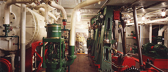
Engineering, Building, and Architecture

Not many museums collect houses. The National Museum of American History has four, as well as two outbuildings, 11 rooms, an elevator, many building components, and some architectural elements from the White House. Drafting manuals are supplemented by many prints of buildings and other architectural subjects. The breadth of the museum's collections adds some surprising objects to these holdings, such as fans, purses, handkerchiefs, T-shirts, and other objects bearing images of buildings.

The engineering artifacts document the history of civil and mechanical engineering in the United States. So far, the Museum has declined to collect dams, skyscrapers, and bridges, but these and other important engineering achievements are preserved through blueprints, drawings, models, photographs, sketches, paintings, technical reports, and field notes.

Joseph Francis of New York (1801–93) made a name for himself in the 1840s and 1850s manufacturing light and sturdy corrugated-iron lifeboats and other nautical gear. This 1841 patent model shows his design for a wood or metal boat fitted with airtight copper tanks.
Description
Joseph Francis of New York (1801–93) made a name for himself in the 1840s and 1850s manufacturing light and sturdy corrugated-iron lifeboats and other nautical gear. This 1841 patent model shows his design for a wood or metal boat fitted with airtight copper tanks. These tanks were to be charged with gas or air to provide buoyancy and, in an emergency, would work in conjunction with several holes through the bottom of the boat. When the boat started taking on water in rough seas, the holes would be opened. That action, combined with the buoyancy of the tanks, would permit drainage.
The well-known inventors of mid-19th-century America—Elias Howe, Cyrus McCormick, and Samuel F. B. Morse—were celebrated as national benefactors. Aspiring inventors regarded applying for a patent not just as a key step on the road to potential wealth, but as a patriotic duty—a contribution to the country’s betterment and future. Solidly within this style, Joseph Francis confidently called his buoyant boat the “great American life boat.” He declared with pride that “the model and application of the buoyant power which I now claim . . . is the best and safest for life boats and all other boats and vessels . . . it is different from and an improvement on all former invention by me and any other person . . . .”
In fact, the 1841 patent represented by this model is but a minor alteration to his first patent, an 1839 design for a double-bottomed boat fitted with buoyant air cylinders. His second attempt simply added additional tanks to the boat’s ends and flattened the bottom of the hull to enable it “to sit upright when left by a retiring surge upon a rock bar or beach, where other modeled boats would be upset.”
Date made
1841
patent date
1841-03-26
patentee
Francis, Joseph
inventor
Francis, Joseph
ID Number
TR.308542
catalog number
308542
accession number
89797
patent number
2,018
Text and photograph from Gardner's Photographic Sketchbook of the War, Vol. II. Negative by William R.
Description
Text and photograph from Gardner's Photographic Sketchbook of the War, Vol. II. Negative by William R. Pywell, text and positive by Alexander Gardner.
This sketch represents a portion of the field of the battle of Bull Run, fought on the 21st of July, 1861, by the forces under Gen. McDowell and Gen. Beauregard. In a general order, issued on the 20th, Gen. McDowell said: "The enemy has planted a battery on the Warrenton turnpike to defend the passage of Bull Run; has seized the stone bridge, and made a heavy abatis on the right bank, to oppose our advance in that direction. The ford above the bridge is also guarded, whether with artillery or not, is not positively known, but every indication favors the belief that he proposes to defend the passage of the stream. It is intended to turn the position, force the enemy from the road, that it may be re-opened, and, if possible, destroy the railroad leading from Manasses to the Valley of Virginia, where the enemy has a large force." General McDowell commenced operations with the divisions of Tyler, Hunter, Heintzelman, and Miles-33,000 men; 18,000 of whom were engaged. The strength of the enemy was about the same, and was all engaged. The plan of the attack was for Tyler's division to threaten the passage of the bridge, Miles to make a demonstration at Blackburn's Ford, two miles below, and the divisions of Hunter and Heintzleman to move up the stream ten miles, and by a flank movement surprise and overwhelm the enemy while occupied with the two other divisions.
The country at that time was densely wooded, and the entire portion shown in the sketch occupied by the Confederates. It was expected that Hunter and Heintzelman would strike the left of the enemy at daylight on the 21st, but owing to unforeseen obstacles, failed to reach the designated point until after ten o'clock. This delay revealed the movement to Beauregard, who immediately disposed his forces to meet it by extending them obliquely across the turnpike, facing the bridge, at a distance of about two miles. Hunter, Heintzelman, and Tyler, who had crossed the bridge, attacked the enemy, and the engagement became general; our forces, after a severe struggle, driving him in great confusion from the field, and occupying the turnpike. The fighting had nearly ceased, and Gen. McDowell was expressing his thanks to some of his officers for their services, when Johnston's reinforcements from Winchester suddenly appeared in rear of our right, and threw our lines into utter confusion. A feeble attempt was made to repulse the attack, but the regiments rapidly broke to pieces, and forming a mass of terror-stricken fugitives, rushed from the field down across the bridge, which soon became obstructed by wagons, and to prevent pursuit by the enemy was destroyed. A portion of this ground was fought over in the battles of Gen. Pope in 1862, and hundreds of acres still bear evidences of those fearful scenes.
Location
Currently not on view
date made
1862-03
maker
Gardner, Alexander
ID Number
1986.0711.0334.07
accession number
1986.0711
catalog number
1986.0711.0334.07
This metal steam engine model was made by Greville Bathe in 1913. The horizontal table engine has a vertical cylinder and flywheel.
Description (Brief)
This metal steam engine model was made by Greville Bathe in 1913. The horizontal table engine has a vertical cylinder and flywheel. The donor of this item, Greville Bathe, was a machinist and engine hobbyist who would fashion his own parts to create model engines.
Location
Currently not on view
date made
1913
ID Number
MC.329024
catalog number
329024
accession number
278175
The Weeden no. 102 electric generator was produced by the Weeden Manufacturing Company of New Bedford, Massachusetts from 1913 until 1918. This was an earlier version of the model No. 102, as evidenced by the wooden base plate attached to the cast iron base.
Description (Brief)
The Weeden no. 102 electric generator was produced by the Weeden Manufacturing Company of New Bedford, Massachusetts from 1913 until 1918. This was an earlier version of the model No. 102, as evidenced by the wooden base plate attached to the cast iron base. It is an electromagnetic generator, producing a direct electric current through the rotation of a wire coil in a magnetic field. The generator could be connected to the flywheel of a Weeden steam engine, rotating the center coil, turning mechanical power into electricity.
The Weeden Manufacturing Company was founded in New Bedford, Massachusetts by William M. Weeden in the early 1880s, originally producing a variety of tinplate household items. In 1884 it introduced the Weeden No. 1 Steam engine as “a new and great premium for boys” who were subscribers to the Youth’s Companion magazine. Weeden made over a hundred different models of toy steam engines until the company ceased operations in 1952.
Location
Currently not on view
date made
ca 1900
ID Number
MC.322914
catalog number
322914
accession number
220719
This is a demonstration model of an oscillating cylinder steam engine. It was designed by William Graham of Carlisle, Pennsylvania about 1889.
Description
This is a demonstration model of an oscillating cylinder steam engine. It was designed by William Graham of Carlisle, Pennsylvania about 1889. Graham was awarded United States Patent Number 413,506 on October 22, 1889 for the design of this type engine, and the patent drawings match this model very closely.
An oscillating steam engine differs from a standard engine in that the steam cylinder is pivoted on the engine frame and oscillates up and down about the pivot as its connecting rod operates the crankshaft of the engine. In a standard engine, the cylinder is fixed in orientation, and the piston rod is connected to a crosshead which moves fore and aft within a set of guides. The crosshead in turn is coupled via a pin to the connecting rod which allows it to pivot independently as the crankshaft revolves.
One advantage of an oscillating cylinder design is the engine is relatively compact and occupies less space than a standard engine. Graham made such a claim as a benefit of his patent. He also claimed his design used few parts, was simple in construction and low in construction cost. His patent also included new features for reducing and compensating for wear of the engine steam valve as well as a method for assuring steam-tight attachments where the steam enters and exits through the cylinder’s pivot points. Engines based on this design were built in sizes from 5 to 10 horsepower and were popular in central Pennsylvania for small shop power.
In the image of the model the steam cylinder is seen at the left with its cylinder rod attached directly to the crank arm of the flywheel. The steam valve is the horizontal cylinder on top of and at 90 degrees to the steam cylinder. As the steam cylinder oscillated up and down about its central pivot, the valve was operated by the lever shown extending from its front to a sliding pivot in the slotted vertical frame at the front of the engine. The timing of the valve could be adjusted by the small wheel at the top which moved the pivot point up and down in the slot. The patent drawings show the pivot point was intended to be adjusted by a fly-ball governor.
date made
ca 1880
ID Number
MC.310898
catalog number
310898
accession number
132,179
patent number
413,506
The Bing Company of Bavaria, Germany manufactured this toy steam engine during the early 20th century. The horizontal boiler has a steam whistle and sight glass above a black firebox with a simulated brickwork chimney.
Description (Brief)
The Bing Company of Bavaria, Germany manufactured this toy steam engine during the early 20th century. The horizontal boiler has a steam whistle and sight glass above a black firebox with a simulated brickwork chimney. The boiler powers an orange horizontal slide valve engine and flywheel. Everything is mounted on a tin base that measures 9.25 by 9.5 inches.
The Gebrüder Bing (Bing Brothers) toy company was founded in Nuremburg, Germany by Adolf and Ignatz Bing in 1863 and operated until 1932. The company was renamed Bing Werke (Bing Works) in 1918 when Ignatz Bing died. While very successful from 1863 until 1912, World War I created an unfavorable export market for German products, and the hard post-war years caused additional financial hardships. The harsh political climate in Germany forced the Jewish Bing family to flee to England in 1932, and Bing’s assets were acquired by rival toy company Bub in 1933.
Location
Currently not on view
date made
20th century
ID Number
MC.328991
catalog number
328991
accession number
278175
An engine indicator is an instrument for graphically recording the pressure versus piston displacement through an engine stroke cycle. Engineers use the resulting diagram to check the design and performance of the engine. Manufactured by Crosby Steam Gage & Valve Co.
Description
An engine indicator is an instrument for graphically recording the pressure versus piston displacement through an engine stroke cycle. Engineers use the resulting diagram to check the design and performance of the engine. Manufactured by Crosby Steam Gage & Valve Co. of Boston, Massachusetts, these steam engine indicators are enclosed in a wooden case. Each consists of a steel piston; an interchangeable external, helical wound spring; a large single recording drum with a spiral spring; and a brass stylus. The piston causes the stylus to rise and fall with pressure changes in the engine under measurement thereby directly recording the indicator’s output on the paper. Around the drum’s base is wound a cord that is attached to the connecting rod of the piston on the steam engine being measured. This causes the drum to rotate as the engine’s piston moves. An internal coil spring causes the cord to retract and the drum to counter rotate back to its original position as the connecting rod returns. The result is a steam pressure-volume diagram which is used to measure the efficiency and other attributes of the steam engine. These indicators enabled simultaneous measurement of both ends of a cylinder.
The introduction of the steam indicator in the late 1790s and early 1800s by James Watt and others had a great impact on the understanding of how the steam behaved inside the engine's cylinder and thereby enabled much more exacting and sophisticated designs. The devices also changed how the economics and efficiency of steam engines were portrayed and marketed. They helped the prospective owner of a machine better understand how much his fuel costs would be for a given amount of work performed. Measurement of fuel consumed and work delivered by the engine was begun by Watt, who in part justified the selling price of his engines on the amount of fuel cost the purchaser might save compared to an alternate engine. In the early days of steam power, the method to compare engine performance was based on a concept termed the engine’s “duty”. It originally was calculated as the number of pounds of water raised one foot high per one bushel of coal consumed. The duty method was open to criticism due to its inability to take into consideration finer points of efficiency in real world applications of engines . Accurate determination of fuel used in relation to work performed has been fundamental to the design and improvement of all steam-driven prime movers ever since Watt’s time. And, the steam indicators’ key contribution was the accurate measurements of performance while the engine was actually doing the work it was designed to do. These Crosby steam indicators represented over one hundred years of evolution and improvement of the devices.
Location
Currently not on view
date made
ca 1930
ID Number
MC.335062
catalog number
335062
accession number
314531
This model was submitted to the U.S. Patent Office with the application for the patent issued to William A. Doble, of San Francisco, California, February 7, 1899, no.
Description
This model was submitted to the U.S. Patent Office with the application for the patent issued to William A. Doble, of San Francisco, California, February 7, 1899, no. 619149.
The model represents a small sector of the rotor of a water wheel to which are attached three buckets, which illustrate, generally, the characteristics of the modern [1930s] tangential water-wheel bucket, i. e., the notched lip, the splitter wedge, the curved face and back, and the method of attaching the buckets to the rotor.
The feature of this particular bucket is the form of the curved faces, which are designed to disturb the jets of water as little as possible in any way except in the plane of the wheel’s rotation. The curves are developed upon the theory that the water moving at high velocity has a tendency to remain in one plane, called “kinetic stability”, so that the resultant angles of reaction caused by the reversing curves of the bucket faces are not a normal result of these curves but are divergent therefrom.
Reference:
This description comes from the 1939 Catalog of the Mechanical Collections of the Division of Engineering United States Museum Bulletin 173 by Frank A. Taylor.
Location
Currently not on view
date made
1899
patent date
1899-02-07
inventor
Doble, William A.
ID Number
MC.309207
catalog number
309207
accession number
89797
patent number
619,149
This model was submitted to the U.S. Patent Office with the application for the patent issued to William A. Lighthall, of Albany, New York, October 23, 1849, no.
Description
This model was submitted to the U.S. Patent Office with the application for the patent issued to William A. Lighthall, of Albany, New York, October 23, 1849, no. 6811.
The model shows a combination of a horizontal cylinder with a vertical beam to which the engine’s force is applied between the fulcrum and the connecting rod to the engine crank. It permits locating the propelling machinery of a side-wheel steamboat low within the hull.
The model is a panel representing a horizontal cylinder with piston rod connecting to a short beam pivoted at a point below the level of the cylinder. From a short distance above the point at which the piston force is applied to the beam a long connecting rod connects to the crank on the engine shaft located above the cylinder and at the middle of its length. The location of the condenser below the cylinder and the location of the air pump and the manner of operating it are shown by the model.
Reference:
This description comes from the 1939 Catalog of the Mechanical Collections of the Division of Engineering United States Museum Bulletin 173 by Frank A. Taylor.
Location
Currently not on view
date made
1849
patent date
1849-10-23
inventor
Lighthall, William A.
ID Number
MC.308641
catalog number
308641
accession number
89797
patent number
6,811
This model was filed with the application to the U.S. Patent Office for Patent Number 224,482 issued to Harry M Sciple of Selin's Grove, Pennsylvania on February 10, 1880. The patent was for a new and improved portable steam engine. Mr.
Description
This model was filed with the application to the U.S. Patent Office for Patent Number 224,482 issued to Harry M Sciple of Selin's Grove, Pennsylvania on February 10, 1880. The patent was for a new and improved portable steam engine. Mr. Sciple's goals for his design were lightness, durability and low cost. He claimed his innovation was making the majority of the engine from only two castings. The first and largest was the base, steam cylinder, and steam valve. The second was the cylinder head combined with the crosshead guides. In the image of the model the steam valve is the horizontal cylinder on the side of the steam cylinder; and the crosshead and guides casting is the arch shape at the top. The piston rod is attached to the crosshead which can be seen across the arch. Another new design feature claimed by Mr. Sciple was the use of vee- shaped crosshead guides. Instead of the typical metal sliding on metal crosshead and guide design, he used rubber coated rollers attached to each end of the crosshead. The connecting rod is the inverted u-shaped hoop seen connected to a bar across the crosshead and descending on each side of the cylinder to the crankshaft. The eccentric gear is shown on the shaft just outside the base. The rod connected to it operates the steam valve via the crank arm shown.
Before the widespread use of electric motors, small high-speed steam engines such as the Sciple design were common for general light duty. Simple and dependable, such engines were cheap to build and easy to operate and maintain. They could be connected directly to pumps, generators, blowers and other machinery.
All of the key elements of the patent are illustrated in detail by the model. The patent model parts representing the large castings are made of lead. Other metal is used for the moving parts. Diagrams showing the complete design of the patent can be found in the patent document online at the United States Patent and Trademark Office website, www.uspto.gov.
date made
1880
patent date
1880-02-10
inventor
Sciple, Harry M.
ID Number
MC.308710
catalog number
308710
accession number
89,797
patent number
224,481
This toy steam engine was manufactured by an unknown maker during the early 20th century.
Description (Brief)
This toy steam engine was manufactured by an unknown maker during the early 20th century. The horizontal boiler powers a horizontal, reversible slide valve engine with flywheel, all mounted onto a metal topped wooden block.
Live steam toys enjoyed a period of popularity from the 1880s until the 1930s. The miniature steam engines were marketed as both toys and instructive devices that mimicked full-scale steam-powered machines and allowed every boy and girl to be their own engineer. In toy steam engines, a heating source is introduced into the firebox below the boiler (early toys used lit wicks fueled by denatured alcohol, later toys used electricity) which heated the water to produce the steam pressure that ran the engine. A variety of accessories could be powered by the engine; attachments included windmills, pumps, grinders, and electric lights.
Location
Currently not on view
date made
early 20th century
ID Number
MC.329015
catalog number
329015
accession number
278175
Text and photograph from Gardner's Photographic Sketchbook of the War, Vol. II. Negative by Timothy H. O'Sullivan, text and positive by Alexander Gardner.The commissary at General Headquarters of the Army of the Potomac was nothing less than an immense grocery establishment.
Description
Text and photograph from Gardner's Photographic Sketchbook of the War, Vol. II. Negative by Timothy H. O'Sullivan, text and positive by Alexander Gardner.
The commissary at General Headquarters of the Army of the Potomac was nothing less than an immense grocery establishment. Coffee, tea, sugar, molasses, bacon, salt pork, fresh beef, potatoes, rice, flour, &c., were always kept on hand in large quantities, and of the best quality. This institution was under the charge of Brevet Major J. R. Coxe, whose portly form adorns the photograph of "What do I want, John Henry?" Occasionally some command out of provisions would suddenly call on Major Coxe for a hundred thousand rations or more, and never was the gallant Major found unable to respond. Rain, snow, darkness, fathomless roads, or unexplored forests, never hindered his wagon trains. Upon him depended the sustenance of Headquarters, and the Commissary General and Staff. It was never his fault if they went hungry.
It was interesting in the last year of the war to witness the Virginia families flock to Headquarters for the purpose of purchasing supplies of the Commissary. Decrepit [sic] men, ladies, children, and family servants crowded the Commissary at stated periods for rations, carrying off their purchased provisions in the oddest vehicles, on horseback, and on foot, some individuals every week walking twenty miles to get their supplies. The provisions sold by the Commissary were disposed of at prices far below market rates, the Government only charging the cost price at wholesale; and as great care was taken in the selection of supplies by the Government agents, it was highly desirable to citizens to purchase rations. This was especially the case with respect to tea, coffee, and sugar, which were bought by the Government in as unadulterated a form as could be found.
Location
Currently not on view
date made
1864-02
maker
Gardner, Alexander
ID Number
1986.0711.0283.11
accession number
1986.0711
catalog number
1986.0711.0283.11
This toy grinder was manufactured by the Danish company H. Langes Legetoy around the middle of the 20th century.
Description (Brief)
This toy grinder was manufactured by the Danish company H. Langes Legetoy around the middle of the 20th century. The grinder consists of a cast metal base painted red, with a grindstone in the center that has a shaft and pulley wheel that allows the grindstone to be attached to a power source and spun. H. Langes Legetoy produced a variety of toy machine tools including a trip-hammer, grindstone, drill press, shaper, punch press, circular saw, tumbler, lathe, and grinder. These tools would often be arranged on a single board with a line shaft allowing all the machines to be operated simultaneously from a single power source.
Location
Currently not on view
date made
ca 1950
ID Number
MC.329082
catalog number
329082
accession number
278175
The Weeden Manufacturing Company of New Bedford, Massachusetts produced this Weeden No. 32 toy steam engine during the late 19th century until around 1927.
Description (Brief)
The Weeden Manufacturing Company of New Bedford, Massachusetts produced this Weeden No. 32 toy steam engine during the late 19th century until around 1927. The engine was known as the “Eureka” model, and consisted of a steel jacketed brass boiler with two star cutouts and an overtype horizontal slide valve engine and flywheel. The metal end of the boiler reads “WEEDEN/TRADE MARK/ REG. U.S. PAT. OFF./32/THE WEEDEN/EUREKA.”
The Weeden Manufacturing Company was founded in New Bedford, Massachusetts by William M. Weeden in the early 1880s, originally producing a variety of tinplate household items. In 1884 it introduced the Weeden No. 1 Steam engine as “a new and great premium for boys” who were subscribers to the Youth’s Companion magazine. Weeden made over a hundred different models of toy steam engines until the company ceased operations in 1952.
Location
Currently not on view
date made
early 20th century
ID Number
MC.328966
catalog number
328966
accession number
278175
This General Controls Tempotherm thermostat was manufactured during the 1960s. The thermostat could be programmed for separate temperatures for the day and the night.
Description
This General Controls Tempotherm thermostat was manufactured during the 1960s. The thermostat could be programmed for separate temperatures for the day and the night. The Tempotherm could automatically oscillate between the two temperatures at the desired time.
The ubiquity of thermostats in 21st century homes shrouds the decades of innovation, industrial design, and engineering that went into making them an everyday object in almost every home. In the early 20th century, a majority of American households still heated their homes with manually operated furnaces that required a trip down to the basement and stoking the coal fired furnace. Albert Butz’s “damper-flapper” system was patented in 1886 and allowed home owner to set the thermostat to a certain temperature which would open a damper to the furnace, increasing the fire and heating the house. Progressive innovations allowed for the thermostats to use gas lines, incorporate electricity, turn on at a set time, include heating and cooling in one mechanism, and even connect to the internet.
Location
Currently not on view
ID Number
2008.0011.09
accession number
2008.0011
catalog number
2008.0011.09
George S. Stearns and William Hodgson of Cincinnati, Ohio, submitted a patent application for an improvement in governors for steam engines to the United States Patent Office. They received patent 9,236 on August 31, 1852. A governor regulates the speed of an engine.
Description
George S. Stearns and William Hodgson of Cincinnati, Ohio, submitted a patent application for an improvement in governors for steam engines to the United States Patent Office. They received patent 9,236 on August 31, 1852. A governor regulates the speed of an engine. Their governor was of normal design, but Stearns and Hodgson claimed as new their use of quadrants with teeth at the end of each arm supporting a fly ball. The inventors claimed the advantages of such a design were simplicity of operation and low cost of construction.
The patent model as shown in the image is constructed of cast iron and steel. All of the key elements of the patent are illustrated by the model. It includes a hand crank to permit demonstration of actual operation. A full description of the workings of the governor and diagrams showing the complete design of the patent can be found in the patent document online at the United States Patent and Trademark Office website, www.uspto.gov.
date made
1852
patent date
1852-08-31
inventor
Stearns, George R.
Hodgson, Will
ID Number
MC.251287
catalog number
251287
accession number
48865
patent number
9,236
This model was filed with the application to the U.S. Patent Office for Patent Number 27,979 issued to Henri Giffard of Paris, France on April 24, 1860.
Description
This model was filed with the application to the U.S. Patent Office for Patent Number 27,979 issued to Henri Giffard of Paris, France on April 24, 1860. The patent was for an improved method of supplying water to a steam boiler.
Early boilers operated at such low steam pressures that introducing feed water into the boiler could be done by simple pumps that filled elevated reservoirs. The water flowed into the boiler by its own weight. However, as pressures increased it became necessary to force water into the boiler by increasingly powerful pumps. Giffard’s invention was for a means of injecting the water into the boiler by the force of the steam itself. Unlike pumps, the Giffard injector had no moving parts.
Giffard’s concept was to push a high velocity jet of steam through a small nozzle which was surrounded by an annular space connected to the feed water reservoir. The jet created a partial vacuum which drew water from the reservoir. The mixture of condensed steam and water was then pushed at high speed into a gradually diverging pipe which slowed the flow while maintaining a pressure slightly above the pressure of the steam in the boiler.
In the image of the model steam is supplied to the injector via the pipe and valve at the upper left. The lever at the far left controlled the flow of steam to the nozzle. The larger pipe at the bottom center connected to the reservoir, and the smaller pipe to its right was for unneeded water to return to the reservoir. Glass sight ports between these pipes allowed visual inspection of the flow. The gradually diverging pipe section is between these ports and the exit valve at the upper right.
The patent model is constructed of brass and steel. This model is actually a standard commercial model that was being manufactured in France prior to the patent application. A full description of the operation of the injector along with complete diagrams of the patent can be found in the patent document online at the United States Patent and Trademark Office website, www.uspto.gov.
date made
1860
patent date
1860-04-24
inventor
Giffard, Henry
ID Number
MC.309368
catalog number
309368
accession number
89797
patent number
27,979
This toy steam traction engine was manufactured by Bing Works of Nuremberg, Germany around 1918-1932.
Description (Brief)
This toy steam traction engine was manufactured by Bing Works of Nuremberg, Germany around 1918-1932. The traction engine consists of a firebox below a boiler with a horizontal slide valve engine attached to a flywheel that drives the tractor’s rear wheel.
The Gebrüder Bing (Bing Brothers) toy company was founded in Nuremburg, Germany by Adolf and Ignatz Bing in 1863 and operated until 1932. The company was renamed Bing Werke (Bing Works) in 1918 when Ignatz Bing died. While very successful from 1863 until 1912, World War I created an unfavorable export market for German products, and the hard post-war years created additional financial hardships. The harsh political climate in Germany forced the Jewish Bing family to flee to England in 1932, and Bing’s assets were acquired by rival toy company Bub in 1933.
Location
Currently not on view
ID Number
MC.335707
catalog number
335707
accession number
1977.0920
This De Juhasz gas engine indicator, serial number 407, consists of a small steel piston with three grooves; a vented brass cylinder with radial fins for cooling; an external, double wound spring, which can be changed; a light Bakelite drum with a spiral spring and a single recor
Description
This De Juhasz gas engine indicator, serial number 407, consists of a small steel piston with three grooves; a vented brass cylinder with radial fins for cooling; an external, double wound spring, which can be changed; a light Bakelite drum with a spiral spring and a single record; and a metal stylus. This is a new instrument, complete with metal box and accessories.
An engine indicator is an instrument for graphically recording the pressure versus piston displacement through an engine stroke cycle. Engineers use the resulting diagram to check the design and performance of the engine.
A mechanical indicator consists of a piston, spring, stylus, and recording system. The gas pressure of the cylinder deflects the piston and pushes against the spring, creating a linear relationship between the gas pressure and the deflection of the piston against the spring. The deflection is recorded by the stylus on a rotating drum that is connected to the piston. Most indicators incorporate a mechanical linkage to amplify the movement of the piston to increase the scale of the record.
When the ratio of the frequency of the pressure variation to the natural frequency of the system is small, then the dynamic deflection is equal to the static deflection. To design a system with a high natural frequency, the mass of the piston, spring, stylus, and mechanical linkage must be small, but the stiffness of the spring must be high. The indicator is subjected to high temperatures and pressures and rapid oscillations, imposing a limitation on the reduction in mass. Too stiff a spring will result in a small displacement of the indicator piston and a record too small to measure with accuracy. Multiplication of the displacement will introduce mechanical ad dynamic errors.
The parameters of the problem for designing an accurate and trouble free recorder are such that there is no easy or simple solution. Studying the variety of indicators in the collection shows how different inventors made different compromises in their designs.
Location
Currently not on view
ID Number
1981.0217.01
accession number
1981.0217
catalog number
1981.0217.01
This drill press was manufactured by Wilhelm Schröder GmbH & Company (Wilesco) of Lüdenscheid, Germany during the 20th century. The drill press is a Wilesco model M51.
Description (Brief)
This drill press was manufactured by Wilhelm Schröder GmbH & Company (Wilesco) of Lüdenscheid, Germany during the 20th century. The drill press is a Wilesco model M51. The press could be connected to the drive wheel of a toy steam engine for power and operate just like its full size counterpart.
Location
Currently not on view
date made
mid 20th century
ID Number
MC.329063
catalog number
329063
accession number
278175
This injector was submitted to the U.S. Patent Office with the application for the patent issued to Horace B. Murdock, of Detroit, Michigan, November 11, 1890, no.
Description
This injector was submitted to the U.S. Patent Office with the application for the patent issued to Horace B. Murdock, of Detroit, Michigan, November 11, 1890, no. 440183; assigned to the American Injector Co.
This is a double injector having two force tubes arranged in parallel order and operated with a single actuating shaft. The overflow valves as well as the steam valves of the two sets of tubes are operated by the same shaft so that the steam valve of the first set opens in advance of the steam valve of the second set and the overflow valve of the first set closes in advance of the second set. The stems of all conical plug valves are extended outside of the injector shell and are provided with slotted ends by which they may be turned with a suitable tool to grind upon the valve seats.
Reference:
This description comes from the 1939 Catalog of the Mechanical Collections of the Division of Engineering United States Museum Bulletin 173 by Frank A. Taylor.
Location
Currently not on view
date made
1890
patent date
1890-11-11
inventor
Murdock, Horace B.
ID Number
MC.309186
catalog number
309186
accession number
89797
patent number
440,183
This toy steam engine was made by the Märklin Company during the early 20th century. This toy steam engine consists of a firebox, horizontal brass boiler, chimney stack, and horizontal engine with flyball governor that powers a flywheel.
Description (Brief)
This toy steam engine was made by the Märklin Company during the early 20th century. This toy steam engine consists of a firebox, horizontal brass boiler, chimney stack, and horizontal engine with flyball governor that powers a flywheel. The boiler and engine are mounted on a tin base.
The Märklin Company was established in 1859 in the town of Göppingen, Germany by tin smith Theodor Friedrich Wilhelm Märklin. Märklin began his business with the production of tin doll houses, but the company soon began producing a variety of tinplate and metal items, eventually specializing in toys that included steam engines such as this one.
Location
Currently not on view
date made
mid 20th century
ID Number
MC.329031
catalog number
329031
accession number
278175
This model was submitted to the U.S. Patent Office with the application for the patent issued to H. Uhry and H. A. Luttgens, of Paterson, New Jersey, March 20, 1855, no. 12564.The model represents a “link motion” applicable to marine, locomotive, or stationary steam engine.
Description
This model was submitted to the U.S. Patent Office with the application for the patent issued to H. Uhry and H. A. Luttgens, of Paterson, New Jersey, March 20, 1855, no. 12564.
The model represents a “link motion” applicable to marine, locomotive, or stationary steam engine. It is a combination of three eccentrics, the ordinary Stephenson link motion, an additional link pivoted to the Stephenson link, a differential rocker, and a main rocker. The main rocker and the Stephenson link operate one valve, which distributes steam to the cylinder, supplies outside lead, and cuts off the steam in proportion to the decrease of travel. The valve operated by the differential rocker exhausts the steam and opens and cuts off the admission of steam near full stroke of the piston.
Reference:
This description comes from the 1939 Catalog of the Mechanical Collections of the Division of Engineering United States Museum Bulletin 173 by Frank A. Taylor.
Location
Currently not on view
date made
1855
patent date
1855-03-20
inventor
Uhry, H.
ID Number
MC.308656
catalog number
308656
accession number
89797
patent number
12,564
This toy steam engine was manufactured by the Doll Company of Nuremberg, Germany during the early 20th century. The toy steam engine is model number 354. The vertical engine is mounted on an iron base, with vertical firebox, boiler, and chimney.
Description (Brief)
This toy steam engine was manufactured by the Doll Company of Nuremberg, Germany during the early 20th century. The toy steam engine is model number 354. The vertical engine is mounted on an iron base, with vertical firebox, boiler, and chimney. The vertical engine is shafted to a flywheel.
Live steam toys enjoyed a period of popularity from the 1880s until the 1930s. The miniature steam engines were marketed as both toys and instructive devices that mimicked full-scale steam-powered machines and allowed every boy and girl to be their own engineer. In toy steam engines, a heating source is introduced into the firebox below the boiler (early toys used lit wicks fueled by denatured alcohol, later toys used electricity) which heated the water to produce the steam pressure that ran the engine. A variety of accessories could be powered by the engine; attachments included windmills, pumps, grinders, and electric lights.
Location
Currently not on view
date made
early 20th century
ID Number
MC.328937
catalog number
328937
accession number
278175

Our collection database is a work in progress. We may update this record based on further research and review. Learn more about our approach to sharing our collection online.

If you would like to know how you can use content on this page, see the Smithsonian's Terms of Use. If you need to request an image for publication or other use, please visit Rights and Reproductions.