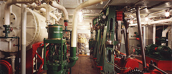
Engineering, Building, and Architecture

Not many museums collect houses. The National Museum of American History has four, as well as two outbuildings, 11 rooms, an elevator, many building components, and some architectural elements from the White House. Drafting manuals are supplemented by many prints of buildings and other architectural subjects. The breadth of the museum's collections adds some surprising objects to these holdings, such as fans, purses, handkerchiefs, T-shirts, and other objects bearing images of buildings.

The engineering artifacts document the history of civil and mechanical engineering in the United States. So far, the Museum has declined to collect dams, skyscrapers, and bridges, but these and other important engineering achievements are preserved through blueprints, drawings, models, photographs, sketches, paintings, technical reports, and field notes.

This metal steam engine model was made by Greville Bathe in 1913. The horizontal table engine has a vertical cylinder and flywheel.
Description (Brief)
This metal steam engine model was made by Greville Bathe in 1913. The horizontal table engine has a vertical cylinder and flywheel. The donor of this item, Greville Bathe, was a machinist and engine hobbyist who would fashion his own parts to create model engines.
Location
Currently not on view
date made
1913
ID Number
MC.329024
catalog number
329024
accession number
278175
The Weeden no. 102 electric generator was produced by the Weeden Manufacturing Company of New Bedford, Massachusetts from 1913 until 1918. This was an earlier version of the model No. 102, as evidenced by the wooden base plate attached to the cast iron base.
Description (Brief)
The Weeden no. 102 electric generator was produced by the Weeden Manufacturing Company of New Bedford, Massachusetts from 1913 until 1918. This was an earlier version of the model No. 102, as evidenced by the wooden base plate attached to the cast iron base. It is an electromagnetic generator, producing a direct electric current through the rotation of a wire coil in a magnetic field. The generator could be connected to the flywheel of a Weeden steam engine, rotating the center coil, turning mechanical power into electricity.
The Weeden Manufacturing Company was founded in New Bedford, Massachusetts by William M. Weeden in the early 1880s, originally producing a variety of tinplate household items. In 1884 it introduced the Weeden No. 1 Steam engine as “a new and great premium for boys” who were subscribers to the Youth’s Companion magazine. Weeden made over a hundred different models of toy steam engines until the company ceased operations in 1952.
Location
Currently not on view
date made
ca 1900
ID Number
MC.322914
catalog number
322914
accession number
220719
This is a demonstration model of an oscillating cylinder steam engine. It was designed by William Graham of Carlisle, Pennsylvania about 1889.
Description
This is a demonstration model of an oscillating cylinder steam engine. It was designed by William Graham of Carlisle, Pennsylvania about 1889. Graham was awarded United States Patent Number 413,506 on October 22, 1889 for the design of this type engine, and the patent drawings match this model very closely.
An oscillating steam engine differs from a standard engine in that the steam cylinder is pivoted on the engine frame and oscillates up and down about the pivot as its connecting rod operates the crankshaft of the engine. In a standard engine, the cylinder is fixed in orientation, and the piston rod is connected to a crosshead which moves fore and aft within a set of guides. The crosshead in turn is coupled via a pin to the connecting rod which allows it to pivot independently as the crankshaft revolves.
One advantage of an oscillating cylinder design is the engine is relatively compact and occupies less space than a standard engine. Graham made such a claim as a benefit of his patent. He also claimed his design used few parts, was simple in construction and low in construction cost. His patent also included new features for reducing and compensating for wear of the engine steam valve as well as a method for assuring steam-tight attachments where the steam enters and exits through the cylinder’s pivot points. Engines based on this design were built in sizes from 5 to 10 horsepower and were popular in central Pennsylvania for small shop power.
In the image of the model the steam cylinder is seen at the left with its cylinder rod attached directly to the crank arm of the flywheel. The steam valve is the horizontal cylinder on top of and at 90 degrees to the steam cylinder. As the steam cylinder oscillated up and down about its central pivot, the valve was operated by the lever shown extending from its front to a sliding pivot in the slotted vertical frame at the front of the engine. The timing of the valve could be adjusted by the small wheel at the top which moved the pivot point up and down in the slot. The patent drawings show the pivot point was intended to be adjusted by a fly-ball governor.
date made
ca 1880
ID Number
MC.310898
catalog number
310898
accession number
132,179
patent number
413,506
The Bing Company of Bavaria, Germany manufactured this toy steam engine during the early 20th century. The horizontal boiler has a steam whistle and sight glass above a black firebox with a simulated brickwork chimney.
Description (Brief)
The Bing Company of Bavaria, Germany manufactured this toy steam engine during the early 20th century. The horizontal boiler has a steam whistle and sight glass above a black firebox with a simulated brickwork chimney. The boiler powers an orange horizontal slide valve engine and flywheel. Everything is mounted on a tin base that measures 9.25 by 9.5 inches.
The Gebrüder Bing (Bing Brothers) toy company was founded in Nuremburg, Germany by Adolf and Ignatz Bing in 1863 and operated until 1932. The company was renamed Bing Werke (Bing Works) in 1918 when Ignatz Bing died. While very successful from 1863 until 1912, World War I created an unfavorable export market for German products, and the hard post-war years caused additional financial hardships. The harsh political climate in Germany forced the Jewish Bing family to flee to England in 1932, and Bing’s assets were acquired by rival toy company Bub in 1933.
Location
Currently not on view
date made
20th century
ID Number
MC.328991
catalog number
328991
accession number
278175
This model was filed with the application to the U.S. Patent Office for Patent Number 224,482 issued to Harry M Sciple of Selin's Grove, Pennsylvania on February 10, 1880. The patent was for a new and improved portable steam engine. Mr.
Description
This model was filed with the application to the U.S. Patent Office for Patent Number 224,482 issued to Harry M Sciple of Selin's Grove, Pennsylvania on February 10, 1880. The patent was for a new and improved portable steam engine. Mr. Sciple's goals for his design were lightness, durability and low cost. He claimed his innovation was making the majority of the engine from only two castings. The first and largest was the base, steam cylinder, and steam valve. The second was the cylinder head combined with the crosshead guides. In the image of the model the steam valve is the horizontal cylinder on the side of the steam cylinder; and the crosshead and guides casting is the arch shape at the top. The piston rod is attached to the crosshead which can be seen across the arch. Another new design feature claimed by Mr. Sciple was the use of vee- shaped crosshead guides. Instead of the typical metal sliding on metal crosshead and guide design, he used rubber coated rollers attached to each end of the crosshead. The connecting rod is the inverted u-shaped hoop seen connected to a bar across the crosshead and descending on each side of the cylinder to the crankshaft. The eccentric gear is shown on the shaft just outside the base. The rod connected to it operates the steam valve via the crank arm shown.
Before the widespread use of electric motors, small high-speed steam engines such as the Sciple design were common for general light duty. Simple and dependable, such engines were cheap to build and easy to operate and maintain. They could be connected directly to pumps, generators, blowers and other machinery.
All of the key elements of the patent are illustrated in detail by the model. The patent model parts representing the large castings are made of lead. Other metal is used for the moving parts. Diagrams showing the complete design of the patent can be found in the patent document online at the United States Patent and Trademark Office website, www.uspto.gov.
date made
1880
patent date
1880-02-10
inventor
Sciple, Harry M.
ID Number
MC.308710
catalog number
308710
accession number
89,797
patent number
224,481
This toy steam engine was manufactured by an unknown maker during the early 20th century.
Description (Brief)
This toy steam engine was manufactured by an unknown maker during the early 20th century. The horizontal boiler powers a horizontal, reversible slide valve engine with flywheel, all mounted onto a metal topped wooden block.
Live steam toys enjoyed a period of popularity from the 1880s until the 1930s. The miniature steam engines were marketed as both toys and instructive devices that mimicked full-scale steam-powered machines and allowed every boy and girl to be their own engineer. In toy steam engines, a heating source is introduced into the firebox below the boiler (early toys used lit wicks fueled by denatured alcohol, later toys used electricity) which heated the water to produce the steam pressure that ran the engine. A variety of accessories could be powered by the engine; attachments included windmills, pumps, grinders, and electric lights.
Location
Currently not on view
date made
early 20th century
ID Number
MC.329015
catalog number
329015
accession number
278175
This toy grinder was manufactured by the Danish company H. Langes Legetoy around the middle of the 20th century.
Description (Brief)
This toy grinder was manufactured by the Danish company H. Langes Legetoy around the middle of the 20th century. The grinder consists of a cast metal base painted red, with a grindstone in the center that has a shaft and pulley wheel that allows the grindstone to be attached to a power source and spun. H. Langes Legetoy produced a variety of toy machine tools including a trip-hammer, grindstone, drill press, shaper, punch press, circular saw, tumbler, lathe, and grinder. These tools would often be arranged on a single board with a line shaft allowing all the machines to be operated simultaneously from a single power source.
Location
Currently not on view
date made
ca 1950
ID Number
MC.329082
catalog number
329082
accession number
278175
The Weeden Manufacturing Company of New Bedford, Massachusetts produced this Weeden No. 32 toy steam engine during the late 19th century until around 1927.
Description (Brief)
The Weeden Manufacturing Company of New Bedford, Massachusetts produced this Weeden No. 32 toy steam engine during the late 19th century until around 1927. The engine was known as the “Eureka” model, and consisted of a steel jacketed brass boiler with two star cutouts and an overtype horizontal slide valve engine and flywheel. The metal end of the boiler reads “WEEDEN/TRADE MARK/ REG. U.S. PAT. OFF./32/THE WEEDEN/EUREKA.”
The Weeden Manufacturing Company was founded in New Bedford, Massachusetts by William M. Weeden in the early 1880s, originally producing a variety of tinplate household items. In 1884 it introduced the Weeden No. 1 Steam engine as “a new and great premium for boys” who were subscribers to the Youth’s Companion magazine. Weeden made over a hundred different models of toy steam engines until the company ceased operations in 1952.
Location
Currently not on view
date made
early 20th century
ID Number
MC.328966
catalog number
328966
accession number
278175
George S. Stearns and William Hodgson of Cincinnati, Ohio, submitted a patent application for an improvement in governors for steam engines to the United States Patent Office. They received patent 9,236 on August 31, 1852. A governor regulates the speed of an engine.
Description
George S. Stearns and William Hodgson of Cincinnati, Ohio, submitted a patent application for an improvement in governors for steam engines to the United States Patent Office. They received patent 9,236 on August 31, 1852. A governor regulates the speed of an engine. Their governor was of normal design, but Stearns and Hodgson claimed as new their use of quadrants with teeth at the end of each arm supporting a fly ball. The inventors claimed the advantages of such a design were simplicity of operation and low cost of construction.
The patent model as shown in the image is constructed of cast iron and steel. All of the key elements of the patent are illustrated by the model. It includes a hand crank to permit demonstration of actual operation. A full description of the workings of the governor and diagrams showing the complete design of the patent can be found in the patent document online at the United States Patent and Trademark Office website, www.uspto.gov.
date made
1852
patent date
1852-08-31
inventor
Stearns, George R.
Hodgson, Will
ID Number
MC.251287
catalog number
251287
accession number
48865
patent number
9,236
This model was filed with the application to the U.S. Patent Office for Patent Number 27,979 issued to Henri Giffard of Paris, France on April 24, 1860.
Description
This model was filed with the application to the U.S. Patent Office for Patent Number 27,979 issued to Henri Giffard of Paris, France on April 24, 1860. The patent was for an improved method of supplying water to a steam boiler.
Early boilers operated at such low steam pressures that introducing feed water into the boiler could be done by simple pumps that filled elevated reservoirs. The water flowed into the boiler by its own weight. However, as pressures increased it became necessary to force water into the boiler by increasingly powerful pumps. Giffard’s invention was for a means of injecting the water into the boiler by the force of the steam itself. Unlike pumps, the Giffard injector had no moving parts.
Giffard’s concept was to push a high velocity jet of steam through a small nozzle which was surrounded by an annular space connected to the feed water reservoir. The jet created a partial vacuum which drew water from the reservoir. The mixture of condensed steam and water was then pushed at high speed into a gradually diverging pipe which slowed the flow while maintaining a pressure slightly above the pressure of the steam in the boiler.
In the image of the model steam is supplied to the injector via the pipe and valve at the upper left. The lever at the far left controlled the flow of steam to the nozzle. The larger pipe at the bottom center connected to the reservoir, and the smaller pipe to its right was for unneeded water to return to the reservoir. Glass sight ports between these pipes allowed visual inspection of the flow. The gradually diverging pipe section is between these ports and the exit valve at the upper right.
The patent model is constructed of brass and steel. This model is actually a standard commercial model that was being manufactured in France prior to the patent application. A full description of the operation of the injector along with complete diagrams of the patent can be found in the patent document online at the United States Patent and Trademark Office website, www.uspto.gov.
date made
1860
patent date
1860-04-24
inventor
Giffard, Henry
ID Number
MC.309368
catalog number
309368
accession number
89797
patent number
27,979
This toy steam traction engine was manufactured by Bing Works of Nuremberg, Germany around 1918-1932.
Description (Brief)
This toy steam traction engine was manufactured by Bing Works of Nuremberg, Germany around 1918-1932. The traction engine consists of a firebox below a boiler with a horizontal slide valve engine attached to a flywheel that drives the tractor’s rear wheel.
The Gebrüder Bing (Bing Brothers) toy company was founded in Nuremburg, Germany by Adolf and Ignatz Bing in 1863 and operated until 1932. The company was renamed Bing Werke (Bing Works) in 1918 when Ignatz Bing died. While very successful from 1863 until 1912, World War I created an unfavorable export market for German products, and the hard post-war years created additional financial hardships. The harsh political climate in Germany forced the Jewish Bing family to flee to England in 1932, and Bing’s assets were acquired by rival toy company Bub in 1933.
Location
Currently not on view
ID Number
MC.335707
catalog number
335707
accession number
1977.0920
This drill press was manufactured by Wilhelm Schröder GmbH & Company (Wilesco) of Lüdenscheid, Germany during the 20th century. The drill press is a Wilesco model M51.
Description (Brief)
This drill press was manufactured by Wilhelm Schröder GmbH & Company (Wilesco) of Lüdenscheid, Germany during the 20th century. The drill press is a Wilesco model M51. The press could be connected to the drive wheel of a toy steam engine for power and operate just like its full size counterpart.
Location
Currently not on view
date made
mid 20th century
ID Number
MC.329063
catalog number
329063
accession number
278175
This toy steam engine was made by the Märklin Company during the early 20th century. This toy steam engine consists of a firebox, horizontal brass boiler, chimney stack, and horizontal engine with flyball governor that powers a flywheel.
Description (Brief)
This toy steam engine was made by the Märklin Company during the early 20th century. This toy steam engine consists of a firebox, horizontal brass boiler, chimney stack, and horizontal engine with flyball governor that powers a flywheel. The boiler and engine are mounted on a tin base.
The Märklin Company was established in 1859 in the town of Göppingen, Germany by tin smith Theodor Friedrich Wilhelm Märklin. Märklin began his business with the production of tin doll houses, but the company soon began producing a variety of tinplate and metal items, eventually specializing in toys that included steam engines such as this one.
Location
Currently not on view
date made
mid 20th century
ID Number
MC.329031
catalog number
329031
accession number
278175
This toy steam engine was manufactured by the Doll Company of Nuremberg, Germany during the early 20th century. The toy steam engine is model number 354. The vertical engine is mounted on an iron base, with vertical firebox, boiler, and chimney.
Description (Brief)
This toy steam engine was manufactured by the Doll Company of Nuremberg, Germany during the early 20th century. The toy steam engine is model number 354. The vertical engine is mounted on an iron base, with vertical firebox, boiler, and chimney. The vertical engine is shafted to a flywheel.
Live steam toys enjoyed a period of popularity from the 1880s until the 1930s. The miniature steam engines were marketed as both toys and instructive devices that mimicked full-scale steam-powered machines and allowed every boy and girl to be their own engineer. In toy steam engines, a heating source is introduced into the firebox below the boiler (early toys used lit wicks fueled by denatured alcohol, later toys used electricity) which heated the water to produce the steam pressure that ran the engine. A variety of accessories could be powered by the engine; attachments included windmills, pumps, grinders, and electric lights.
Location
Currently not on view
date made
early 20th century
ID Number
MC.328937
catalog number
328937
accession number
278175
This toy grindstone and figure was produced by Fleischmann during the 1960s. The grindstone has a pulley that could be connected to a steam engine’s flywheel to provide power to the grindstone.
Description (Brief)
This toy grindstone and figure was produced by Fleischmann during the 1960s. The grindstone has a pulley that could be connected to a steam engine’s flywheel to provide power to the grindstone. The man is connected to the grindstone in such a way that it seems as if he is turning the wheel while it is powered by an engine.
Location
Currently not on view
ID Number
MC.329068
catalog number
329068
accession number
278175
This model was filed with the application to the U.S. Patent Office for Patent Number 4,289 issued to R.F. Loper of Philadelphia, Pennsylvania on November 26, 1845. The patent was for a new method for allowing a single steam engine to operate two parallel crankshafts.
Description
This model was filed with the application to the U.S. Patent Office for Patent Number 4,289 issued to R.F. Loper of Philadelphia, Pennsylvania on November 26, 1845. The patent was for a new method for allowing a single steam engine to operate two parallel crankshafts. One shaft would turn clockwise and the other would turn counterclockwise.
This was an important feature for marine engines powering a ship with twin propellers. Having twin propellers turning in the same direction would increase the tendency for the boat to veer off course due to the torque effect of the propellers. This would require the ship's rudder to compensate, thereby reducing efficiency. With counter revolving propellers, one with right-hand pitch and the other with left-hand pitch, this adverse effect is eliminated.
The patent model is constructed of brass, steel and wood. All of the key elements of the patent are illustrated by the model, and it was built such that the motion of the engine could be demonstrated. A full description of the operation of the engine along with complete diagrams of the patent can be found in the patent document online at the United States Patent and Trademark Office website, www.uspto.gov.
date made
1845
patent date
1845-11-26
inventor
Loper, R. F.
ID Number
MC.251297
catalog number
251297
patent number
4,289
accession number
48865
This model was filed with the application to the U.S. Patent Office for Patent Number 169,249 issued to Samuel B. Frank of Marshall, Missouri on October 26, 1875. The patent was for an opposed piston steam engine with four pistons.
Description
This model was filed with the application to the U.S. Patent Office for Patent Number 169,249 issued to Samuel B. Frank of Marshall, Missouri on October 26, 1875. The patent was for an opposed piston steam engine with four pistons. The goal of the design was to reduce vibration caused by unbalanced reciprocating masses.
The four pistons were equally spaced within a single cylinder, and each cylinder traversed one fourth of the length of the cylinder. The two inner pistons were arranged to move towards each other while the outer pistons would move away from each other. The reverse order would take place on the next cycle. A single slide valve with multiple ports fed steam to the appropriate volumes between the pistons. Each piston had its own crosshead, two on the left of the engine and two on the right. Concentric piston rods were used to allow the rods for the outer pistons to pass inside those for the inner pistons.
The use of the two pairs of opposed pistons was claimed to reduce vibration, and Frank also claimed the engine would be more powerful than standard engines. As shown in the image the design was complex and had many moving parts and wearing surfaces. It is not known how practical the design was to manufacture and operate. A search of available literature did not produce any examples of actual use of the patent.
The patent model is made of brass and mounted on a wood base. It is highly detailed and illustrates all of the key details of the patent. A full description of the operation of the engine along with complete diagrams of the patent can be found in the patent document online at the United States Patent and Trademark Office website, www.uspto.gov.
date made
ca 1870
patent date
1875-10-26
inventor
Frank, Samuel B.
ID Number
MC.321889
accession number
245986
patent number
169,249
catalog number
321889
This model was filed with the application to the U.S. Patent Office for Patent Number 39,756 issued to Hermann Shlarbaum of New York, New York on September 1, 1863. The patent was for an improvement in oscillating steam engines.
Description
This model was filed with the application to the U.S. Patent Office for Patent Number 39,756 issued to Hermann Shlarbaum of New York, New York on September 1, 1863. The patent was for an improvement in oscillating steam engines. An oscillating steam engine differs from a standard engine in that the steam cylinder is pivoted on the engine frame and oscillates back and forth about the pivot as its connecting rod operates the crankshaft of the engine. In a standard engine, the cylinder is fixed in orientation, and the piston rod moves fore and aft within a crosshead which allows the connecting rod to pivot independently as the crankshaft revolves.
Mr. Shlarbaum did not claim his overall design as new. Others had patented very similar designs. His claim was for the unique design of the steam and exhaust valves for the engine. The claimed benefits of this design included simplicity and economy of manufacture, operation and maintenance. The inventor also claimed that his design avoided having lubricating oil in the pivot being overheated by high pressure steam.
The patent model is constructed of cast iron and brass. All of the key elements of the patent are illustrated by the model to include the valve mechanism. A full description of the workings of the engine and diagrams showing the complete design of the patent can be found in the patent document online at the United States Patent and Trademark Office website, www.uspto.gov.
date made
ca 1863
patent date
1863-09-01
inventor
Shlarbaum, Herrmann
ID Number
MC.251293
catalog number
251293
patent number
39,756
accession number
48865
This model was filed with the application to the U.S. Patent Office for Patent Number 24,897 issued to Charles A. Wilson of Cincinnati, Ohio on July 26, 1859. His patent was for a new and improved concept of stacking long, narrow boxes as elements for a steam radiator .
Description
This model was filed with the application to the U.S. Patent Office for Patent Number 24,897 issued to Charles A. Wilson of Cincinnati, Ohio on July 26, 1859. His patent was for a new and improved concept of stacking long, narrow boxes as elements for a steam radiator . The claimed benefit of this modular design was the ability to tailor the amount of radiator surface area in accordance with the amount of heating needed for a given room. And, this was made possible without changing the amount of floor space required for the radiator. His design called for the boxes, or modules, to be constructed of cast iron with corrugations at the top and bottom that allowed them to nest together tightly while still allowing for expansion and contraction with varying temperature. Each box had holes on the bottom at each end of the box. On the top of each box, nozzles projected upward and aligned with these holes allowing steam to pass from one section to the next. Two vertical screw bolts passed through the holes and nozzles to secure the stack of boxes together. Raised circular bumps surrounded each nozzle and provided a surface for a red lead or other gasket material to seal the joints. Steam entered and exited the radiator via two additional holes on the bottom of the lowest module. Research of available trade literature and other sources has not revealed any commercial product that may have made use of Mr. Wilson’s invention.
The model is constructed of painted tinplate and consists of four modules, or boxes. Steam inlet/outlet holes are modeled at the bottom. The bosses between sections are also shown. The sections are held together with two screw bolts with nuts at the bottom. There is a small, rectangular access plate on the rear of the top section. The patent drawing shows this access; however, its purpose is not described.
Location
Currently not on view
patent date
1859-07-26
inventor
Wilson, Charles A.
ID Number
MC.251778
accession number
48890
catalog number
251778
patent number
24,897
This model was filed with the application to the U.S. Patent Office for Patent Number 29,642 issued to G.W. Van Deren of Bigflats, New York on August 14, 1860. The patent was for a steam engine design employing an oscillating piston.
Description
This model was filed with the application to the U.S. Patent Office for Patent Number 29,642 issued to G.W. Van Deren of Bigflats, New York on August 14, 1860. The patent was for a steam engine design employing an oscillating piston. Instead of the more common straight cylinder with a piston within, Van Deren employed two pistons within a semi-circular cylinder. The pistons were connected by a curved rod with a pin in the middle for attachment of the connecting rod to the crankshaft. A steam valve above the cylinder admitted and exhausted steam alternatively for one, then the other piston. This caused a rocking motion of the pistons, and the connecting rod imparted rotation to the flywheel via the crank arm. This eliminated the need for crossheads and slides.
The inventor claimed that his design reduced stresses on the engine at the end of each cycle of the pistons and thus allowed operation at higher speeds. He also claimed reduced costs of construction. A search of available material did not reveal any commercial use of Van Deren’s design. He held two additional patents for components of oscillating steam engines.
The patent model is constructed of iron and steel. All of the key elements of the patent are illustrated by the model which demonstrates the engine motion. In the image the steam valve housing is the horizontal cylinder at the top of the model. The inlet is the orange pipe and the exhaust is from the top of the valve housing. The engine’s cylinder containing the pistons is the green semi-circular structure below the steam valve housing. The horizontal steel rod in front is the connecting rod from the pistons to the crankshaft. The valve gear eccentric is shown on the crankshaft on the right with its connected rods and levers to operate the valve. Diagrams showing the complete design of the patent can be found in the patent document online at the United States Patent and Trademark Office website, www.uspto.gov.
date made
1860
patent date
1860-08-14
inventor
Van Deren, G. W.
ID Number
MC.308663
catalog number
308663
accession number
89797
patent number
29,642
This toy steam engine was manufactured by an unknown maker during the early 20th century. The engine has a reversible slide valve and flywheel, with a horizontal brass boiler.Live steam toys enjoyed a period of popularity from the 1880s until the 1930s.
Description (Brief)
This toy steam engine was manufactured by an unknown maker during the early 20th century. The engine has a reversible slide valve and flywheel, with a horizontal brass boiler.
Live steam toys enjoyed a period of popularity from the 1880s until the 1930s. The miniature steam engines were marketed as both toys and instructive devices that mimicked full-scale steam-powered machines and allowed every boy and girl to be their own engineer. In toy steam engines, a heating source is introduced into the firebox below the boiler (early toys used lit wicks fueled by denatured alcohol, later toys used electricity) which heated the water to produce the steam pressure that ran the engine. A variety of accessories could be powered by the engine; attachments included windmills, pumps, grinders, and electric lights.
Location
Currently not on view
date made
early 20th century
ID Number
MC.329014
catalog number
329014
accession number
278175
This toy punch press was manufactured by the Danish company H. Langes Legetoy around the middle of the 20th century. The press has a base made of cast metal painted red, with a flywheel that drives the press up and down. H.
Description (Brief)
This toy punch press was manufactured by the Danish company H. Langes Legetoy around the middle of the 20th century. The press has a base made of cast metal painted red, with a flywheel that drives the press up and down. H. Langes Legetoy produced a variety of toy machine tools including a trip-hammer, grindstone, drill press, shaper, punch press, circular saw, tumbler, lathe, and grinder. These tools would often be arranged on a single board with a line shaft allowing all the machines to be operated simultaneously from a single power source.
Location
Currently not on view
date made
ca 1950
ID Number
MC.329078
catalog number
329078
accession number
278175
This Weeden toy steam engine was produced by the Weeden Manufacturing Company of New Bedford, Massachusetts from the late 19th to early 20th century. The engine is possibly model number 18. The engine consists of a vertical brass boiler and horizontal slide valve engine.
Description (Brief)
This Weeden toy steam engine was produced by the Weeden Manufacturing Company of New Bedford, Massachusetts from the late 19th to early 20th century. The engine is possibly model number 18. The engine consists of a vertical brass boiler and horizontal slide valve engine. The engine is mounted on a green metal stand, which is attached to a brown tin base that measures 7.5 inches by 10.5 inches.
The Weeden Manufacturing Company was founded in New Bedford, Massachusetts by William M. Weeden in the early 1880s, originally producing a variety of tinplate household items. In 1884 it introduced the Weeden No. 1 Steam engine as “a new and great premium for boys” who were subscribers to the Youth’s Companion magazine. Weeden made over a hundred different models of toy steam engines until the company ceased operations in 1952.
Location
Currently not on view
date made
early 20th century
ID Number
MC.328962
catalog number
328962
accession number
278175
This toy steam engine was made by an unknown German manufacturer during the early 20th century. The horizontal steam boiler powers a flywheel which is connected to a dynamo that can power the attached bulb.
Description (Brief)
This toy steam engine was made by an unknown German manufacturer during the early 20th century. The horizontal steam boiler powers a flywheel which is connected to a dynamo that can power the attached bulb. The boiler, flywheel, dynamo, and light bulb are all attached to the wooden base.
Live steam toys enjoyed a period of popularity from the 1880s until the 1930s. The miniature steam engines were marketed as both toys and instructive devices that mimicked full-scale steam-powered machines and allowed every boy and girl to be their own engineer. In toy steam engines, a heating source is introduced into the firebox below the boiler (early toys used lit wicks fueled by denatured alcohol, later toys used electricity) which heated the water to produce the steam pressure that ran the engine. A variety of accessories could be powered by the engine; attachments included windmills, pumps, grinders, and electric lights.
Location
Currently not on view
date made
early 20th century
ID Number
ER.328990
accession number
278175
catalog number
328990

Our collection database is a work in progress. We may update this record based on further research and review. Learn more about our approach to sharing our collection online.

If you would like to know how you can use content on this page, see the Smithsonian's Terms of Use. If you need to request an image for publication or other use, please visit Rights and Reproductions.