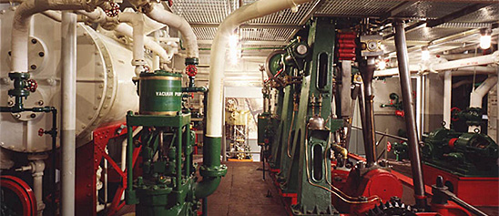
Engineering, Building, and Architecture

Not many museums collect houses. The National Museum of American History has four, as well as two outbuildings, 11 rooms, an elevator, many building components, and some architectural elements from the White House. Drafting manuals are supplemented by many prints of buildings and other architectural subjects. The breadth of the museum's collections adds some surprising objects to these holdings, such as fans, purses, handkerchiefs, T-shirts, and other objects bearing images of buildings.

The engineering artifacts document the history of civil and mechanical engineering in the United States. So far, the Museum has declined to collect dams, skyscrapers, and bridges, but these and other important engineering achievements are preserved through blueprints, drawings, models, photographs, sketches, paintings, technical reports, and field notes.

This indicator, designed to meet the requirements of early 20th century high-speed engines, employs the lightest construction consistent with strength and accuracy.
Description
This indicator, designed to meet the requirements of early 20th century high-speed engines, employs the lightest construction consistent with strength and accuracy. It is equipped with a reducing wheel, which is a self-contained device capable of reducing engine strokes of 14 to 72 inches to the proper stroke of the paper drum.
The cylinder of this indicator is supported so that its lower end is free and its longitudinal expansion or contraction is unimpeded. The annular space between the cylinder and the casing is designed to serve as a steam jacket. The piston is an extremely thin steel shell with shallow channels on its outer surface to provide steam packing and moisture lubrication. The piston rod is hollow and is connected to the pencil mechanism by means of a swivel head that can be screwed in or out of the rod to adjust the position of the diagram on the paper. The pencil mechanism is kinematically a pantograph that theoretically gives the pencil point a movement exactly parallel to the piston and the amount of the movement of the piston is multiplied six times at the pencil point. The design of the piston spring is peculiar to this indicator. It is made of a single piece of spring steel wire wound from the middle into a double coil, the ends of which are screwed into a metal head drilled helically to receive the spring.
The exact strength of spring is obtained by screwing the spring into the head more or less, when they are firmly fixed. The foot of the spring is a small steel bead firmly pinned to the straight portion of wire at the bottom of the spring. This takes the place of the heavier brass foot used in earlier indicators.*
An engine indicator is an instrument for graphically recording the pressure versus piston displacement through an engine stroke cycle. Engineers use the resulting diagram to check the design and performance of the engine.
A mechanical indicator consists of a piston, spring, stylus, and recording system. The gas pressure of the cylinder deflects the piston and pushes against the spring, creating a linear relationship between the gas pressure and the deflection of the piston against the spring. The deflection is recorded by the stylus on a rotating drum that is connected to the piston. Most indicators incorporate a mechanical linkage to amplify the movement of the piston to increase the scale of the record.
When the ratio of the frequency of the pressure variation to the natural frequency of the system is small, then the dynamic deflection is equal to the static deflection. To design a system with a high natural frequency, the mass of the piston, spring, stylus, and mechanical linkage must be small, but the stiffness of the spring must be high. The indicator is subjected to high temperatures and pressures and rapid oscillations, imposing a limitation on the reduction in mass. Too stiff a spring will result in a small displacement of the indicator piston and a record too small to measure with accuracy. Multiplication of the displacement will introduce mechanical ad dynamic errors.
The parameters of the problem for designing an accurate and trouble free recorder are such that there is no easy or simple solution. Studying the variety of indicators in the collection shows how different inventors made different compromises in their designs.
*Reference:
This description comes from the 1939 Catalog of the Mechanical Collections of the Division of Engineering United States Museum Bulletin 173 by Frank A. Taylor.
Location
Currently not on view
ID Number
MC.309833
catalog number
309833
accession number
109635
The largest artifact in the museum, this Georgian-style, 2 ½-story timber-framed house was built in the 1760s and stood at 16 Elm Street in the center of Ipswich, Massachusetts, until 1963 when efforts by Ipswich citizens saved it from the bulldozer.
Description
The largest artifact in the museum, this Georgian-style, 2 ½-story timber-framed house was built in the 1760s and stood at 16 Elm Street in the center of Ipswich, Massachusetts, until 1963 when efforts by Ipswich citizens saved it from the bulldozer. The house was carefully taken apart—the frame, chimney, and many other pieces were shipped to the Museum and reassembled.
Today, the house is the centerpiece of the exhibition Within These Walls…, and visitors are able to peer through its walls, windows, and doors to view settings played out against the backdrop of Colonial America, the American Revolution, the abolitionist movement, the industrial era, and World War II. The exhibition tells the story of five ordinary families, selected from many, who lived in this house over 200 years and made history in their kitchens and parlors, through everyday choices and personal acts of courage and sacrifice.
date made
ca 1760
resident
Caldwell, Josiah
Caldwell, Lucy
Choate, Abraham
Choate, Sarah
Dodge, Abraham
Dodge, Bethiah
Lynch, Catherine
Lynch, Mary
owner
Dodge, Abraham
Caldwell, Josiah
Choate, Sarah
Dodge, Bethiah
Caldwell, Lucy
Lynch, Catherine
Lynch, Mary
resident
Scott, Mary
owner
Choate, Abraham
ID Number
DL.64.545
catalog number
64.545
accession number
252318
Crosby Steam Gauge & Valve Co. of Boston, Massachusetts, manufactured this steam engine indicator, serial number 3309. It consists of a piston, which is stuck inside the cylinder. A brass stylus can record onto a large small drum with a spiral spring and a single record.
Description
Crosby Steam Gauge & Valve Co. of Boston, Massachusetts, manufactured this steam engine indicator, serial number 3309. It consists of a piston, which is stuck inside the cylinder. A brass stylus can record onto a large small drum with a spiral spring and a single record. Accompanying the indicator is a box with twelve springs and a spring wrench.
An engine indicator is an instrument for graphically recording the pressure versus piston displacement through an engine stroke cycle. Engineers use the resulting diagram to check the design and performance of the engine.
A mechanical indicator consists of a piston, spring, stylus, and recording system. The gas pressure of the cylinder deflects the piston and pushes against the spring, creating a linear relationship between the gas pressure and the deflection of the piston against the spring. The deflection is recorded by the stylus on a rotating drum that is connected to the piston. Most indicators incorporate a mechanical linkage to amplify the movement of the piston to increase the scale of the record.
When the ratio of the frequency of the pressure variation to the natural frequency of the system is small, then the dynamic deflection is equal to the static deflection. To design a system with a high natural frequency, the mass of the piston, spring, stylus, and mechanical linkage must be small, but the stiffness of the spring must be high. The indicator is subjected to high temperatures and pressures and rapid oscillations, imposing a limitation on the reduction in mass. Too stiff a spring will result in a small displacement of the indicator piston and a record too small to measure with accuracy. Multiplication of the displacement will introduce mechanical ad dynamic errors.
The parameters of the problem for designing an accurate and trouble free recorder are such that there is no easy or simple solution. Studying the variety of indicators in the collection shows how different inventors made different compromises in their designs.
Location
Currently not on view
maker
Crosby Steam Gage & Valve Company
ID Number
MC.316795
catalog number
316795
accession number
228496
Crosby Steam Gauge & Valve Co. of Boston, Massachusetts, manufactured this steam engine indicator, serial number 1074D.
Description
Crosby Steam Gauge & Valve Co. of Boston, Massachusetts, manufactured this steam engine indicator, serial number 1074D. It consists of a steel piston; a vented brass cylinder; an external, double wound spring, which can be changed; a large drum with a spiral spring and a single record; and a brass stylus. Accompanying the indicator is a box with twelve springs and some small tools.
An engine indicator is an instrument for graphically recording the pressure versus piston displacement through an engine stroke cycle. Engineers use the resulting diagram to check the design and performance of the engine.
A mechanical indicator consists of a piston, spring, stylus, and recording system. The gas pressure of the cylinder deflects the piston and pushes against the spring, creating a linear relationship between the gas pressure and the deflection of the piston against the spring. The deflection is recorded by the stylus on a rotating drum that is connected to the piston. Most indicators incorporate a mechanical linkage to amplify the movement of the piston to increase the scale of the record.
When the ratio of the frequency of the pressure variation to the natural frequency of the system is small, then the dynamic deflection is equal to the static deflection. To design a system with a high natural frequency, the mass of the piston, spring, stylus, and mechanical linkage must be small, but the stiffness of the spring must be high. The indicator is subjected to high temperatures and pressures and rapid oscillations, imposing a limitation on the reduction in mass. Too stiff a spring will result in a small displacement of the indicator piston and a record too small to measure with accuracy. Multiplication of the displacement will introduce mechanical ad dynamic errors.
The parameters of the problem for designing an accurate and trouble free recorder are such that there is no easy or simple solution. Studying the variety of indicators in the collection shows how different inventors made different compromises in their designs.
Location
Currently not on view
maker
Crosby Steam Gage & Valve Company
ID Number
MC.316797
catalog number
316797
accession number
228496
patent number
1074D
This model was filed with the application to the U.S. Patent Office for Patent Number 100,211 issued to B. F. Sturtevant of Jamaica Plains, MA on February 22, 1870.
Description
This model was filed with the application to the U.S. Patent Office for Patent Number 100,211 issued to B. F. Sturtevant of Jamaica Plains, MA on February 22, 1870. The patent described a forced air heating system consisting of a steam producing boiler, a steam engine to drive a centrifugal wheel fan for circulating air, a heat exchanger to heat the air via the combustion products of the boiler, a condenser utilizing the circulating air to return the steam to water for reuse, and a series of duct work and valves. The patent model illustrates only the central duct work, heat exchanger and steam condenser. Diagrams showing the complete heating and ventilating apparatus design can be found in the patent document online (www.USPTO.gov/patents/process/search/index.jsp). In the image the upper cylinder is the steam condenser. The cylinder at the bottom represents the heat exchanger. The opening at its front is where the combustion gases from the boiler would exit via a flue or chimney. Cold air entered at the ducts at the lower right. Two separate intakes are shown – the bottom was for fresh air from outside the building and the upper for recirculated air from heated rooms. A valve allowed engineers to regulate the ratio of outside to inside air. Hot air exited at the right side of the condenser via the ductwork which was connected to the engine-driven fan’s inlet. The heated, pressurized air exited from the fan into a series of ducts that would supply heat to various parts of the building. The patent also made provisions for domestic water heating by utilizing some of the condenser’s hot water for that purpose. Sturtevant claimed his design increased efficiency by making use of hot flue gases as the primary source to heat air but also by using the remaining energy of the steam in the condenser to further heat the air. Sturtevant was extremely successful with this and his other patents (no less than 10 patents dealing with heating and ventilation were granted to him on the same day as this patent). In 1860 he founded the B. F. Sturtevant Co. which was extremely successful and long lived; Westinghouse bought the company in 1945, and operations continued at the Hyde Park, MA factory until its closing in 1989. The company’s equipment was installed in many public and private buildings including the U.S. Capitol and the “New National Museum, Washington, D.C” – now the Smithsonian National Museum of Natural History.
The patent model is constructed of brass and tin. It represents the central duct work, heat exchanger, and steam condenser of Sturtevant’s patent. The flue pipes are modelled inside the heat exchanger. The valves controlling the mixture of fresh and recirculated air are present within the inlet duct. A model of the pipe carrying exhaust steam to the condenser is also included.
Location
Currently not on view
date made
ca 1870
patent date
1870-02-22
inventor
Sturtevant, B. F.
ID Number
MC.308725
catalog number
308725
accession number
89797
patent number
100,211
This model was submitted with the application to the U.S. Patent Office for the Patent no. 46084, issued to Moses G.
Description
This model was submitted with the application to the U.S. Patent Office for the Patent no. 46084, issued to Moses G. Crane, of Newtown, Massachusetts, January 31, 1865.
This engine consists of one vertical work cylinder and two pump or air-transfer cylinders connected to two furnaces. In operation two separate quantities of air are used repeatedly. One quantity of air is circulated between one furnace and the upper end of the work cylinder by one of the air pumps, while the other charge of air is supplied from the other furnace to the lower end of the work cylinder. In each case the air is heated in the furnace, transferred to the work cylinder, allowed to expand doing work against the piston, and is then returned to the furnace by the pump, to be reheated. The pump pistons and valves are actuated by slotted bell cranks on the ends of the engine crankshaft.
Reference:
This description comes from the 1939 Catalog of the Mechanical Collections of the Division of Engineering United States Museum Bulletin 173 by Frank A. Taylor.
Location
Currently not on view
date made
1865
patent date
1865-01-31
inventor
Crane, Moses G.
ID Number
MC.308670
catalog number
308670
accession number
89797
patent number
46,084
This model represents a skeletonized taper plug in which are formed two gridiron valve seats and a bonnet that carried a rockarm collar and cams for actuating one steam and one exhaust valve on the valve seats.
Description
This model represents a skeletonized taper plug in which are formed two gridiron valve seats and a bonnet that carried a rockarm collar and cams for actuating one steam and one exhaust valve on the valve seats. The valves are long narrow gridiron valves, which reciprocate in the direction parallel to the axis of the plug. They are actuated by rods and slides and roller cams, which are rock shaft on the collar. The steam valve slide has a disengaging pawl to provide an adjustable cut-off.
Reference:
This description comes from the 1939 Catalog of the Mechanical Collections of the Division of Engineering United States Museum Bulletin 173 by Frank A. Taylor.
Location
Currently not on view
ID Number
MC.310250
catalog number
310250
accession number
108073
This model was submitted to the U.S. Patent Office with the application for the patent issued to Benaiah Fitts, of Worcester, Massachusetts, August 9, 1859, no. 25005.The model represents a globular valve in which a conical rotor uncovers a port in a conical seat.
Description
This model was submitted to the U.S. Patent Office with the application for the patent issued to Benaiah Fitts, of Worcester, Massachusetts, August 9, 1859, no. 25005.
The model represents a globular valve in which a conical rotor uncovers a port in a conical seat. It operates without a stuffing box and is designed so that the pressure of steam on the rotor is balanced, reducing friction to a minimum.
Reference:
This description comes from the 1939 Catalog of the Mechanical Collections of the Division of Engineering United States Museum Bulletin 173 by Frank A. Taylor.
Location
Currently not on view
date made
1859
patent date
1859-08-09
inventor
Fitts, Benaiah
ID Number
ER.308662
accession number
89797
catalog number
308662
patent number
25,005
Crosby Steam Gauge & Valve Co. of Boston, Massachusetts, manufactured this steam engine indicator, serial number 10021.
Description
Crosby Steam Gauge & Valve Co. of Boston, Massachusetts, manufactured this steam engine indicator, serial number 10021. It consists of a steel piston with four grooves, a vented brass cylinder, an internal spring (which is missing), a small drum with a spiral spring and a single record, and a brass stylus. Accompanying the indicator is a box with twelve springs, double wound.
An engine indicator is an instrument for graphically recording the pressure versus piston displacement through an engine stroke cycle. Engineers use the resulting diagram to check the design and performance of the engine.
A mechanical indicator consists of a piston, spring, stylus, and recording system. The gas pressure of the cylinder deflects the piston and pushes against the spring, creating a linear relationship between the gas pressure and the deflection of the piston against the spring. The deflection is recorded by the stylus on a rotating drum that is connected to the piston. Most indicators incorporate a mechanical linkage to amplify the movement of the piston to increase the scale of the record.
When the ratio of the frequency of the pressure variation to the natural frequency of the system is small, then the dynamic deflection is equal to the static deflection. To design a system with a high natural frequency, the mass of the piston, spring, stylus, and mechanical linkage must be small, but the stiffness of the spring must be high. The indicator is subjected to high temperatures and pressures and rapid oscillations, imposing a limitation on the reduction in mass. Too stiff a spring will result in a small displacement of the indicator piston and a record too small to measure with accuracy. Multiplication of the displacement will introduce mechanical ad dynamic errors.
The parameters of the problem for designing an accurate and trouble free recorder are such that there is no easy or simple solution. Studying the variety of indicators in the collection shows how different inventors made different compromises in their designs.
Location
Currently not on view
ID Number
MC.316796
catalog number
316796
accession number
228496
patent number
10021
Crosby Steam Gauge & Valve Co. of Boston, Massachusetts, manufactured this steam engine indicator, serial number 6163.
Description
Crosby Steam Gauge & Valve Co. of Boston, Massachusetts, manufactured this steam engine indicator, serial number 6163. It consists of a small steel piston (1/8 inch); a vented brass cylinder; an internal, double wound spring, which can be changed; a small drum with a spiral spring and a single record; and a brass stylus. Accompanying the indicator is a box with fourteen springs, small tools, and an extra piston with top stem.
An engine indicator is an instrument for graphically recording the pressure versus piston displacement through an engine stroke cycle. Engineers use the resulting diagram to check the design and performance of the engine.
A mechanical indicator consists of a piston, spring, stylus, and recording system. The gas pressure of the cylinder deflects the piston and pushes against the spring, creating a linear relationship between the gas pressure and the deflection of the piston against the spring. The deflection is recorded by the stylus on a rotating drum that is connected to the piston. Most indicators incorporate a mechanical linkage to amplify the movement of the piston to increase the scale of the record.
When the ratio of the frequency of the pressure variation to the natural frequency of the system is small, then the dynamic deflection is equal to the static deflection. To design a system with a high natural frequency, the mass of the piston, spring, stylus, and mechanical linkage must be small, but the stiffness of the spring must be high. The indicator is subjected to high temperatures and pressures and rapid oscillations, imposing a limitation on the reduction in mass. Too stiff a spring will result in a small displacement of the indicator piston and a record too small to measure with accuracy. Multiplication of the displacement will introduce mechanical ad dynamic errors.
The parameters of the problem for designing an accurate and trouble free recorder are such that there is no easy or simple solution. Studying the variety of indicators in the collection shows how different inventors made different compromises in their designs.
Location
Currently not on view
maker
Crosby Steam Gage & Valve Company
ID Number
MC.316799
catalog number
316799
accession number
228496
patent number
6163
This model was submitted with the application for the patent issued to Thomas B. Dexter, of Lynn, Massachusetts (assignor of one-half his right to the Gilmanton Mills, Belmont, New Hampshire), August 19, 1879, no.
Description
This model was submitted with the application for the patent issued to Thomas B. Dexter, of Lynn, Massachusetts (assignor of one-half his right to the Gilmanton Mills, Belmont, New Hampshire), August 19, 1879, no. 218619.
The model represents a tubular burner with a slightly reduced tip, provided with a vertical diaphragm that divides the burner into two sections. The space on one side of the diaphragm is connected to the oil line and to an air inlet pipe provided with a damper for adjusting the flow of air. The other space is connected to the steam line. In operation the flow of steam from the tip creates suction enough to draw the oil and air through the burner. The oil and air are heated by contact with the diaphragm, which separates them from the steam, and are intimately mixed when they issue from the burner. The diaphragm is notched just inside the tip so that the mixing of the steam and the air and oil results in the formation of a wide, thin, horizontal sheet. This produced a sheet of flame that spread over a large part of the furnace.
Reference:
This description comes from the 1939 Catalog of the Mechanical Collections of the Division of Engineering United States Museum Bulletin 173 by Frank A. Taylor.
Location
Currently not on view
date made
1879
patent date
1879-08-19
inventor
Dexter, Thomas B.
ID Number
MC.308765
catalog number
308765
accession number
89797
patent number
218,619
This steam gauge was made by the Crosby Steam and Gage & Valve Company of Boston, Massachusetts around 1908. It is 8 ½ inches in diameter and nickel plated.
Description
This steam gauge was made by the Crosby Steam and Gage & Valve Company of Boston, Massachusetts around 1908. It is 8 ½ inches in diameter and nickel plated. The gauge was a gift of the Quincy Mining Company of Hancock, Michigan.
For pressures of less than about one atmosphere (15 pounds per square inch), simple mercury columns were adequate as indicators. With the use of high pressure engines and boilers many types of gauges were introduced. In all of these the pressure of the steam acted against a spring loaded piston or diaphragm to move a pointer.
This is a Bourdon type gauge. This type, one of the first truly successful gauges, was invented in 1849 by Eugene Bourdon of France, a curved tube, elliptical in cross section, was used. When pressurized, the ellipse tended to become more circular, causing a slight straightening of the tube exactly proportional to the pressure. The free end of the tube was linked to the indicating pointer. Bourdon gauges remained in widespread use well into the 20th century.
date made
ca 1908
ID Number
MC.319574
catalog number
319574
accession number
244877
serial number
698575
This patent model accompanied John Howarth’s patent application that received patent number 117,290 on July 25, The patent describes a process for extracting sulphate of lime (gypsum) from salt brine (concentrated sea water) by evaporating the brine and then superheating it.Curre
Description
This patent model accompanied John Howarth’s patent application that received patent number 117,290 on July 25, The patent describes a process for extracting sulphate of lime (gypsum) from salt brine (concentrated sea water) by evaporating the brine and then superheating it.
Location
Currently not on view
Date made
1871
patent date
1871-07-25
patentee
Howarth, John
inventor
Howarth, John
ID Number
1999.0086.01
catalog number
1999.0086.01
accession number
1999.0086
patent number
117,290
This model was submitted to the U.S. Patent Office with the application for the patent issued to Robert Leuchsenring, of New Bedford, Massachusetts, March 9, 1880, no.
Description
This model was submitted to the U.S. Patent Office with the application for the patent issued to Robert Leuchsenring, of New Bedford, Massachusetts, March 9, 1880, no. 225226.
This is a form of engine in which a drum-shaped rotor turns in a casing, which is eccentric to the center of the drum, so that the drum runs against one part of the casing and a crescent-shaped annular space is formed between the casing and the drum. Water is admitted tangentially to the drum to one side of and away from the point at which the drum and casing meet. The water impinges upon abutments on the drum, turns the drum, and discharges from the engine about two-thirds of the way around the casing. The abutments on the drum slide into the drum to pass the casing and are held against the casings by springs.
Reference:
This description comes from the 1939 Catalog of the Mechanical Collections of the Division of Engineering United States Museum Bulletin 173 by Frank A. Taylor.
Location
Currently not on view
date made
1880
patent date
1880-03-09
inventor
Leuchsenring, Robert
ID Number
MC.308709
catalog number
308709
accession number
89797
patent number
225,226
The Star Brass Mfg. Co. manufactured this steam engine indicator, serial number 485. It consists of a steel piston; a steel cylinder; an external spring, which is missing; a small drum with a spiral spring and a single record. The stylus is missing, but is likely a pencil point.
Description
The Star Brass Mfg. Co. manufactured this steam engine indicator, serial number 485. It consists of a steel piston; a steel cylinder; an external spring, which is missing; a small drum with a spiral spring and a single record. The stylus is missing, but is likely a pencil point. The accompanying box has five double wound springs.
An engine indicator is an instrument for graphically recording the pressure versus piston displacement through an engine stroke cycle. Engineers use the resulting diagram to check the design and performance of the engine.
A mechanical indicator consists of a piston, spring, stylus, and recording system. The gas pressure of the cylinder deflects the piston and pushes against the spring, creating a linear relationship between the gas pressure and the deflection of the piston against the spring. The deflection is recorded by the stylus on a rotating drum that is connected to the piston. Most indicators incorporate a mechanical linkage to amplify the movement of the piston to increase the scale of the record.
When the ratio of the frequency of the pressure variation to the natural frequency of the system is small, then the dynamic deflection is equal to the static deflection. To design a system with a high natural frequency, the mass of the piston, spring, stylus, and mechanical linkage must be small, but the stiffness of the spring must be high. The indicator is subjected to high temperatures and pressures and rapid oscillations, imposing a limitation on the reduction in mass. Too stiff a spring will result in a small displacement of the indicator piston and a record too small to measure with accuracy. Multiplication of the displacement will introduce mechanical ad dynamic errors.
The parameters of the problem for designing an accurate and trouble free recorder are such that there is no easy or simple solution. Studying the variety of indicators in the collection shows how different inventors made different compromises in their designs.
Location
Currently not on view
ID Number
MC.316802
catalog number
316802
accession number
228496
This model represents the first major controlled circulation boiler in the United States. It was installed at the Somerset, Massachusetts Station of the Montaup Electric Company in 1942.
Description
This model represents the first major controlled circulation boiler in the United States. It was installed at the Somerset, Massachusetts Station of the Montaup Electric Company in 1942. Shortly thereafter the controlled circulation concept reached full commercial development and was widely used in public utility central stations throughout the world.
The history of steam power is one of increasing steam pressures in search of increased efficiency. However, with higher pressures the natural circulation of water of varying densities within the boiler's many circuits becomes less effective.
In controlled circulation boilers, water is continuously and rapidly circulated by pumps which are completely independent of the feed water pumps and thus operate with a relatively small pressure differential. By forcing the water's circulation, the elements of the boiler can be located without regard to hydraulic head, and because frictional loss is not a consideration, smaller tubes can be used. Further, heat is transferred from the fire to the water more efficiently.
The actual boiler this model represents could produce 650,000 pounds of steam per hour at 2,000 pounds per square inch pressure. It contained a volume of 7,800 gallons of water which the pumps could recirculate in just one minute.
date made
1941-1942
ID Number
MC.326787
catalog number
326787
accession number
263167
Unlike most of the half-hull models in the Smithsonian’s National Watercraft Collection, this one was not intended for use in shipbuilding. Instead, this half model of the fishing schooner Helen B. Thomas was made to show a radical design innovation to potential vessel owners.
Description
Unlike most of the half-hull models in the Smithsonian’s National Watercraft Collection, this one was not intended for use in shipbuilding. Instead, this half model of the fishing schooner Helen B. Thomas was made to show a radical design innovation to potential vessel owners. Its maker, Thomas F. McManus, a naval architect in Boston, adapted an idea from sailing yachts to the fishing schooners of New England. He eliminated the bowsprit, the spar projecting forward from the schooner’s bow, in an attempt to make the vessel safer for the fishermen working in treacherous conditions far offshore. In McManus’s new design, fishermen would not have to clamber out on the bowsprit to tend the jib (the vessel’s forward-most sail), a dangerous task especially in bad weather that, in McManus’s view, resulted too often in injury or death.
McManus made this half-hull model and displayed it in his Boston office, hoping to attract a client. After nearly a year, Capt. William Thomas of Portland, Maine, decided to try the design and contracted with the Oxner & Story yard in Essex, Mass., to build the schooner. The Helen B. Thomas was launched in 1902 and measured 106’-7” overall, with a beam (width) of 21’-6” and 13’ deep. The vessel became a successful fishing schooner. While no other schooners were built to this exact design, many were built without the bowsprit, a schooner design that became known as the “knockabout.”
date made
1901
Associated Date
early 20th century
ship built from model design
1902
Captain who contracted the design
Thomas, William
contractors who built the ship
Oxner & Story
maker
McManus, Thomas F.
ID Number
TR.310888
catalog number
310888
accession number
131237
This model was filed with the application to the U.S. Patent Office for the patent issued to Lucius J. Knowles, of Worcester, Massachusetts, April 1, 1879, no.
Description
This model was filed with the application to the U.S. Patent Office for the patent issued to Lucius J. Knowles, of Worcester, Massachusetts, April 1, 1879, no. 231823.
The model represents the steam cylinders of a duplex pump fitted with what the inventor calls auxiliary engines to operate the valves of each cylinder when it is desired to use one cylinder of a duplex pump without the other. Actually the piston of the auxiliary engine is the valve of the main cylinder and the invention is in effect a one cylinder “simplex” pump with steam-actuated valve. This is one of the earliest uses of the steam-actuated valve for steam pumps.
The auxiliary cylinder forms the steam chest and valve ports of the main cylinder while the auxiliary piston acts as the valve. The auxiliary piston has its own valve system, which consists of ports in the auxiliary cylinder wall connected to the main steam passages and so located that they will register with openings in the auxiliary piston when the auxiliary piston is given a slight twist at the end of the main piston’s stroke. These openings connect to passages in the auxiliary cylinder to cause the auxiliary piston to move to the other end of the cylinder and so reverse the stroke of the main piston.
Lucius James Knowles (July 2, 1819 – February 26, 1884) originated and developed the Knowles Steam Pump Co. and the L. J. Knowles & Brother Loom Works at Warren, Massachusetts, and Worcester, Massachusetts, both of which became leading organizations in their respective fields. The Knowles steam pump was one of the best known of the direct-acting pumps, and Knowles is recognized as having contributed much to the final development and refinement of the device. He was one of the first to take up and develop the steam-actuated valve and received several patents for his inventions of improvements in valves.
Reference:
This description comes from the 1939 Catalog of the Mechanical Collections of the Division of Engineering United States Museum Bulletin 173 by Frank A. Taylor.
Location
Currently not on view
date made
1879
patent date
1879-04-01
inventor
Knowles, Lucius J.
ID Number
ER.309250
accession number
89797
patent number
213,823
catalog number
309250
This model represents the fishing schooner Dauntless, built at Essex, Mass., about 1855. Its hull is of the “sharpshooter” type, meaning the bottom has a sharp V-shape, as distinct from the rounded hulls of most fishing craft built in New England.
Description
This model represents the fishing schooner Dauntless, built at Essex, Mass., about 1855. Its hull is of the “sharpshooter” type, meaning the bottom has a sharp V-shape, as distinct from the rounded hulls of most fishing craft built in New England. The model shows the typical deck arrangement for a schooner sailing to or from the offshore fishing grounds, with the dory boats nested together and lashed bottom-up on the deck. All of the sails are set, including the jib and flying jib on the vessel’s long bowsprit.
Fishing on the shallow banks stretching from Georges Bank east of Massachusetts to the Grand Bank off the coast of Newfoundland was a dangerous enterprise. Thousands of lives were lost in the race to catch more fish and deliver them to market before the competition. The demand for fast schooners led to designs that favored speed over safety. The Dauntless is an example of a mid-century schooner with a fast hull and a great deal of sail. The sailing rig would have required crewmen to venture out on the bowsprit to furl the jib, a dangerous proposition, especially in rough weather.
Details of what happened to the Dauntless and its crew in September 1870 are unknown. But the schooner was lost at sea with all hands aboard, while making a passage to the Bay of St. Lawrence from Gloucester. Those lost included Jas. G. Craig, master, John La Pierre, Martin Costello, John Todd Jr., George Todd, Daniel Herrick, Edward Smith, James Smith, James Welch, George Goodwin, and two others, whose names are unknown.
Date made
1894
date made
1855
model built
ca 1855
schooner was lost at sea
1870-09
master of schooner's crew
Craig, Jas. G.
sailor
La Pierre, John
Costello, Martin
Todd, Jr., John
Todd, George
Herrick, Daniel
Smith, Edward
Smith, James
Welch, James
Goodwin, George
ID Number
TR.076244
catalog number
076244
accession number
028022
This model was submitted to the U.S. Patent Office with the application for the patent issued to Andrew J. Peavey of Boston, Massachusetts, August 16, 1870, no.
Description
This model was submitted to the U.S. Patent Office with the application for the patent issued to Andrew J. Peavey of Boston, Massachusetts, August 16, 1870, no. 106400.
The model represents a stationary cylinder filled with oil within which turns a paddle wheel driven by the engine at a speed dependent upon the velocity of the engine. Also within the stationary cylinder and surrounding the paddle wheel is a hollow cylinder, which is hung loosely upon the shaft of the paddle wheel and is free to revolve independently of it. This cylinder has a series of blades or abutments projecting from the inner side of its rim, so that as the paddle wheel causes the oil to revolve in the cylinder the moving oil will come into contact with the abutments and tend to turn the loose cylinder. Attached to the loose cylinder is a pinion that meshes with a toothed sector, which, in turn, is connected with the counterweight and so tends to oppose the turning of that cylinder. As the height to which the counterweight will be raised is a function of the velocity of the engine, this velocity can be governed by properly connecting the counterweight to the cut-off or throttle valve.
Reference:
This description comes from the 1939 Catalog of the Mechanical Collections of the Division of Engineering United States Museum Bulletin 173 by Frank A. Taylor.
Location
Currently not on view
date made
1870
patent date
1870-08-16
inventor
Peavey, Andrew J.
ID Number
ER.308678
accession number
89797
catalog number
308678
patent number
106,400
This model was submitted to the U.S. Patent Office with the application for the patent issued to Joseph W. Fowle, of Boston, Massachusetts, August 14, 1877, no.
Description
This model was submitted to the U.S. Patent Office with the application for the patent issued to Joseph W. Fowle, of Boston, Massachusetts, August 14, 1877, no. 194037.
The model represents a 1-cylinder, vertical marine engine connected to a propeller shaft and propeller in the ordinary manner, with a float or inertia device for closing the throttle valve of the engine each time the vessel in which the engine is installed pitches sufficiently to raise the propeller out of the water.
The gear consists of a heavy weight suspended in suitable guides and stops near the keel of the ship. This weight is not rigidly fixed relative to the ship but tends to float in position as the vessel rises and falls. The change in relative positions actuates a valve lever on an auxiliary steam cylinder and piston, which, in turn, moves the main throttle valve of the engine.
Reference:
This description comes from the 1939 Catalog of the Mechanical Collections of the Division of Engineering United States Museum Bulletin 173 by Frank A. Taylor.
Location
Currently not on view
date made
1877
patent date
1877-08-14
inventor
Fowle, Joseph W.
ID Number
MC.308698
catalog number
308698
accession number
89797
patent number
194,037
This model was submitted to the U.S. Patent Office with the application for the patent issued to Henry Collinson, Boston, Massachusetts, April 13, 1875, no.
Description
This model was submitted to the U.S. Patent Office with the application for the patent issued to Henry Collinson, Boston, Massachusetts, April 13, 1875, no. 161934.
The invention consists of a lid or cover with a true flat face arranged in such a manner that while being forced home against a flat seat it receives a sliding and rotating motion thereon.
The model represents an opening in a plate around which is formed a flat plane face, which forms a seat for the dish –shaped lid or cover. A curved bar of metal spans the opening over the cover and supports a threaded nut through which passes a T-handled screw by which the cover is forced against the seat. At the inner end of the screw is an eccentric head that fits in a recess in the center of the cover, so that turning the screw forces the cover against the seat and moves the center of the cover in a circle, while the friction causes the cover to rotate somewhat about its own center. The result is a combined sliding and rotating of the cover as it is forced against the seat.
Reference:
This description comes from the 1939 Catalog of the Mechanical Collections of the Division of Engineering United States Museum Bulletin 173 by Frank A. Taylor.
Location
Currently not on view
date made
1875
patent date
1875-04-13
inventor
Collinson, Henry
ID Number
ER.309219
accession number
89797
catalog number
309219
patent number
161,934
In places that required many clocks—factories, office and public buildings, or schools—time was often distributed by a system of "master" and "slave" clocks.
Description
In places that required many clocks—factories, office and public buildings, or schools—time was often distributed by a system of "master" and "slave" clocks. In such a system, a central timekeeper, the master clock, sent periodic impulses, usually electric or pneumatic, to any number of secondary or slave clocks. These slave clocks could be located anywhere, without regard for convenience of winding, because they needed none. The master clock could also drive other time signals like classroom bells, factory whistles, or time stamps. More economical to install and more convenient to maintain than an equal number of independent clocks, the system also ensured that all dials within the system agreed.
The museum collection contains such a timekeeping system. The system's master clock (Cat. 310,569), built by E. Howard and Company of Boston, is a mechanical tower clock movement equipped with electrical contacts. Once a minute the escapement, through a pair of rotary switches, closes an electrical circuit and sends an impulse to the slave dial (Cat. 310,570), where electromagnets advance the hands. Batteries at the base of the master clock supply current.
This clock and dial were components of a system that served the Smithsonian between about 1881 and 1932. First housed in the north tower of the Arts and Industries Building, the clock movement distributed impulses to eighteen dials in that building and the Castle, the Smithsonian's earliest building. Tunnels under the floors carried the wiring. The clock room also housed a telephone switchboard, a watchman's clock, a central burglar alarm, and call bells—all of which, like the time distribution system, relied on the newly harnessed power of electricity. "Indeed," boasted the Smithsonian's annual report for 1881, "it is believed that in no building in the world, with the exception of the Grand Opera House in Paris, is there so perfect and complete an application of electricity to practical services."
Date made
1880
manufacturer
E. Howard & Co.
ID Number
ME.310569
catalog number
310569
accession number
123081
Three solid wind wheels drive the armatures of three dynamos, which are in circuit with a small storage battery, an incandescent electric lamp, and switches. This model, constructed by Moses G.
Description
Three solid wind wheels drive the armatures of three dynamos, which are in circuit with a small storage battery, an incandescent electric lamp, and switches. This model, constructed by Moses G. Farmer, electrical pioneer, about 1880, is one of the earliest suggestions of the use of wind power through the medium of the electric generator and storage battery.
Much of the objection to the use of the windmill as a source of power was due to the intermittent nature of its operation. It was thought that it was suited only for pumping water or similar operations where the energy or work produced by the windmill could be stored during periods of useful wind velocities to be used as needed.
Reference:
This description comes from the 1939 Catalog of the Mechanical Collections of the Division of Engineering United States Museum Bulletin 173 by Frank A. Taylor.
Location
Currently not on view
date made
ca 1882
maker
Farmer, Moses G.
ID Number
MC.181985
catalog number
181985
accession number
2015.0173

Our collection database is a work in progress. We may update this record based on further research and review. Learn more about our approach to sharing our collection online.

If you would like to know how you can use content on this page, see the Smithsonian's Terms of Use. If you need to request an image for publication or other use, please visit Rights and Reproductions.