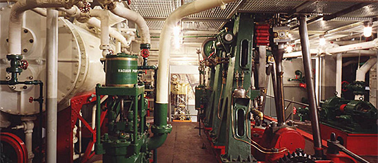
Engineering, Building, and Architecture

Not many museums collect houses. The National Museum of American History has four, as well as two outbuildings, 11 rooms, an elevator, many building components, and some architectural elements from the White House. Drafting manuals are supplemented by many prints of buildings and other architectural subjects. The breadth of the museum's collections adds some surprising objects to these holdings, such as fans, purses, handkerchiefs, T-shirts, and other objects bearing images of buildings.

The engineering artifacts document the history of civil and mechanical engineering in the United States. So far, the Museum has declined to collect dams, skyscrapers, and bridges, but these and other important engineering achievements are preserved through blueprints, drawings, models, photographs, sketches, paintings, technical reports, and field notes.

The Weeden Manufacturing Company of New Bedford, Massachusetts, manufactured the Weeden No. 138 toy steam engine from 1915 until 1933. This Weeden no.
Description (Brief)
The Weeden Manufacturing Company of New Bedford, Massachusetts, manufactured the Weeden No. 138 toy steam engine from 1915 until 1933. This Weeden no. 138 engine consists of a vertical steel boiler and walking beam engine mounted on grey wood, all on a steel base.
The Weeden Manufacturing Company was founded in New Bedford, Massachusetts by William M. Weeden in the early 1880s, originally producing a variety of tinplate household items. In 1884 it introduced the Weeden No. 1 Steam engine as “a new and great premium for boys” who were subscribers to the Youth’s Companion magazine. Weeden made over a hundred different models of toy steam engines until the company ceased operations in 1952.
Location
Currently not on view
date made
ca 1900
ID Number
MC.328951
catalog number
328951
accession number
278175
This Weeden Toy Steam Traction Engine was manufactured by the Weeden Manufacturing Company of New Bedford, Massachusetts from around 1926-1935.
Description (Brief)
This Weeden Toy Steam Traction Engine was manufactured by the Weeden Manufacturing Company of New Bedford, Massachusetts from around 1926-1935. The steam traction engine consists of a black firebox, tin boiler painted brown and horizontal engine powering a flywheel which is chained to the rear wheel. The back of the engine has a steam whistle, and the rear is stamped “WEEDEN/TRADEMARK/U.S. Patent Office.”
The Weeden Manufacturing Company was founded in New Bedford, Massachusetts by William M. Weeden in the early 1880s, originally producing a variety of tinplate household items. In 1884 it introduced the Weeden No. 1 Steam engine as “a new and great premium for boys” who were subscribers to the Youth’s Companion magazine. Weeden made over a hundred different models of toy steam engines until the company ceased operations in 1952.
Location
Currently not on view
date made
ca 1900
ID Number
MC.328928
catalog number
328928
accession number
278175
This toy steam engine consists of a vertical brass boiler with a steam line connected to two horizontal slide valve engines with two flywheels.
Description (Brief)
This toy steam engine consists of a vertical brass boiler with a steam line connected to two horizontal slide valve engines with two flywheels. The museum’s catalogue records indicate that is was possibly made by the Buckman Manufacturing Company, during the late 19th century.
Live steam toys enjoyed a period of popularity from the 1880s until the 1930s. The miniature steam engines were marketed as both toys and instructive devices that mimicked full-scale steam-powered machines and allowed every boy and girl to be their own engineer. In toy steam engines, a heating source is introduced into the firebox below the boiler (early toys used lit wicks fueled by denatured alcohol, later toys used electricity) which heated the water to produce the steam pressure that ran the engine. A variety of accessories could be powered by the engine; attachments included windmills, pumps, grinders, and electric lights.
Location
Currently not on view
date made
late 19th century
ID Number
MC.328982
catalog number
328982
accession number
278175
This toy steam engine was manufactured by the Weeden Manufacturing Company of New Bedford, Massachusetts from around 1884 until the 1940s. The first six Weeden toy steam engine models were all very similar in style, and this model of engine is likely either Weeden No.
Description (Brief)
This toy steam engine was manufactured by the Weeden Manufacturing Company of New Bedford, Massachusetts from around 1884 until the 1940s. The first six Weeden toy steam engine models were all very similar in style, and this model of engine is likely either Weeden No. 1, 2, or 3. The vertical toy steam engine consists of a firebox, boiler, and slide valve engine attached to a wheel. The firebox has been repainted yellow and the boiler has been repainted black.
The Weeden Manufacturing Company was founded in New Bedford, Massachusetts by William M. Weeden in the early 1880s, originally producing a variety of tinplate household items. In 1884 it introduced the Weeden No. 1 Steam engine as “a new and great premium for boys” who were subscribers to the Youth’s Companion magazine. Weeden made over a hundred different models of toy steam engines until the company ceased operations in 1952.
Location
Currently not on view
date made
late 19th century
ID Number
MC.328943
catalog number
328943
accession number
278175
This Peerless brand toy steam engine was made during the early 20th century. The toy consists of a cast iron boiler and a horizontal slide valve engine and flywheel.Currently not on view
Description (Brief)
This Peerless brand toy steam engine was made during the early 20th century. The toy consists of a cast iron boiler and a horizontal slide valve engine and flywheel.
Location
Currently not on view
date made
ca 1900
ID Number
MC.329003
catalog number
329003
accession number
278175
The Weeden no. 102 electric generator was produced by the Weeden Manufacturing Company of New Bedford, Massachusetts from 1913 until 1918. This was an earlier version of the model No. 102, as evidenced by the wooden base plate attached to the cast iron base.
Description (Brief)
The Weeden no. 102 electric generator was produced by the Weeden Manufacturing Company of New Bedford, Massachusetts from 1913 until 1918. This was an earlier version of the model No. 102, as evidenced by the wooden base plate attached to the cast iron base. It is an electromagnetic generator, producing a direct electric current through the rotation of a wire coil in a magnetic field. The generator could be connected to the flywheel of a Weeden steam engine, rotating the center coil, turning mechanical power into electricity.
The Weeden Manufacturing Company was founded in New Bedford, Massachusetts by William M. Weeden in the early 1880s, originally producing a variety of tinplate household items. In 1884 it introduced the Weeden No. 1 Steam engine as “a new and great premium for boys” who were subscribers to the Youth’s Companion magazine. Weeden made over a hundred different models of toy steam engines until the company ceased operations in 1952.
Location
Currently not on view
date made
ca 1900
ID Number
MC.322913
catalog number
322913
accession number
220719
This is a model of an early design for a compound steam engine. A compound steam engine consists of a high pressure cylinder and one or more lower pressure cylinders. The steam exhausted from the high pressure cylinder is used as inlet steam for the next lower pressure cylinder.
Description
This is a model of an early design for a compound steam engine. A compound steam engine consists of a high pressure cylinder and one or more lower pressure cylinders. The steam exhausted from the high pressure cylinder is used as inlet steam for the next lower pressure cylinder. Each cylinder is sized in proportion to its inlet steam pressure so that each produces the same amount of work. Compounding was introduced in 1845 by John McNaught and widely used in many applications from steamship propulsion to powering large electrical generators.
The model represents McNaught’s original approach for the addition of compounding to standard beam engines. The original low pressure steam cylinder is seen at the right with its piston rod attached to the right end of the beam. McNaught added the smaller, high pressure cylinder just to the right of the crankshaft connecting rod at the left end of the beam. Hundreds of engines had their capacity increased by “McNaughting”, and new engines were built on this principle for many years.
date made
mid 19th century
ID Number
MC.315636
catalog number
315636
accession number
220003
This steam gauge was made by the Crosby Steam and Gage & Valve Company of Boston, Massachusetts around 1908. It is 8 ½ inches in diameter and nickel plated.
Description
This steam gauge was made by the Crosby Steam and Gage & Valve Company of Boston, Massachusetts around 1908. It is 8 ½ inches in diameter and nickel plated. The gauge was a gift of the Quincy Mining Company of Hancock, Michigan.
For pressures of less than about one atmosphere (15 pounds per square inch), simple mercury columns were adequate as indicators. With the use of high pressure engines and boilers many types of gauges were introduced. In all of these the pressure of the steam acted against a spring loaded piston or diaphragm to move a pointer.
This is a Bourdon type gauge. This type, one of the first truly successful gauges, was invented in 1849 by Eugene Bourdon of France, a curved tube, elliptical in cross section, was used. When pressurized, the ellipse tended to become more circular, causing a slight straightening of the tube exactly proportional to the pressure. The free end of the tube was linked to the indicating pointer. Bourdon gauges remained in widespread use well into the 20th century.
date made
ca 1908
ID Number
MC.319574
catalog number
319574
accession number
244877
serial number
698575
An engine indicator is an instrument for graphically recording the pressure versus piston displacement through an engine stroke cycle. Engineers use the resulting diagram to check the design and performance of the engine. The James L.
Description
An engine indicator is an instrument for graphically recording the pressure versus piston displacement through an engine stroke cycle. Engineers use the resulting diagram to check the design and performance of the engine. The James L. Robertson & Sons of New York, NY, manufactured this steam indicator about 1900. The indicator is based on a design patented by Joseph W. Thompson which made improvements in the mechanisms driving the recording stylus thus allowing improved measurements of higher speed steam engines. The design also includes elements from another patent by Alpheus O. Lippincott and assigned to Robertson. It dealt with the reduction wheel mechanism below the recording drum. The reduction mechanism allowed for measuring engines with a variety of piston throw lengths.
This indicator set contains within the mahogany box the indicator itself; extra springs of varying stiffness for different steam pressures; a reducing wheel to decrease the piston motion to that required by the indicator drum; sized wooden pulleys for different piston stroke lengths; an extra indicator piston of small diameter for very high pressures; a planimeter for measuring the area of the diagram; servicing tools; and extra blanks. The piston causes the stylus to rise and fall with pressure changes in the engine under measurement thereby directly recording the indicator’s output on the paper. Around the drum’s base is wound a cord that is attached to the connecting rod of the piston on the steam engine being measured. This causes the drum to rotate as the engine’s piston moves. An internal coil spring causes the cord to retract and the drum to counter rotate back to its original position as the connecting rod returns. The result is a steam pressure-volume diagram which is used to measure the efficiency and other attributes of the steam engine.
The introduction of the steam indicator in the late 1790s and early 1800s by James Watt and others had a great impact on the understanding of how the steam behaved inside the engine's cylinder and thereby enabled much more exacting and sophisticated designs. The devices also changed how the economics and efficiency of steam engines were portrayed and marketed. They helped the prospective owner of a machine better understand how much his fuel costs would be for a given amount of work performed.
Measurement of fuel consumed and work delivered by the engine was begun by Watt, who in part justified the selling price of his engines on the amount of fuel cost the purchaser might save compared to an alternate engine. In the early days of steam power, the method to compare engine performance was based on a concept termed the engine’s “duty”. It originally was calculated as the number of pounds of water raised one foot high per one bushel of coal consumed. The duty method was open to criticism due to its inability to take into consideration finer points of efficiency in real world applications of engines. Accurate determination of fuel used in relation to work performed has been fundamental to the design and improvement of all steam-driven prime movers ever since Watt’s time. And, the steam indicators’ key contribution was the accurate measurements of performance while the engine was actually doing the work it was designed to do. This Robertson-Thompson steam indicator represented over one hundred years of evolution and improvement of the devices. Its ability to make recordings for a wide range of engine speeds, pressures and piston stroke lengths was a significant improvement for many applications.
date made
ca 1900
ID Number
MC.315914
catalog number
315914
accession number
222962
Currently not on view
Location
Currently not on view
date made
1902 or later
patent date
1900-03-06
label registration date
1902-11-04
maker
F. Ad. Richter and Company
ID Number
1978.0443.02
accession number
1978.0443
catalog number
1978.0443.02
So popular was the sport of horseracing by the mid 19th century that the animal was frequently illustrated in popular lithographic prints sold for cheap decoration of middle class homes.
Description

So popular was the sport of horseracing by the mid 19th century that the animal was frequently illustrated in popular lithographic prints sold for cheap decoration of middle class homes. The images provided inspiration for makers of weather vanes increasingly displayed on public buildings and barns in rural areas, providing vital information to help farmers plan when to plant or harvest crops. The mold for this weather vane was created by Joseph Wiley Fiske some time after he opened his factories in New York City and Massachusetts between 1858 and 1861. The vane is of gilded copper. The pattern for it was modeled after a Nathaniel Currier print of a famed trotting horse named “Black Hawk.”

Though debate has centered on whether this was “Long Island Black Hawk” or “Vermont Black Hawk,” the popularity of harness racing, also known as horse trotting, at agricultural fairs can not be doubted. By the late 19th century, betting on horses at race tracks had become a popular American pastime as natives and new immigrants gambled their earnings to take a chance on earning a bonus or losing a bundle.

Date made
1850 - 1900
ID Number
CL.65.0924
accession number
261195
catalog number
65.0924
collector/donor number
T-5

Our collection database is a work in progress. We may update this record based on further research and review. Learn more about our approach to sharing our collection online.

If you would like to know how you can use content on this page, see the Smithsonian's Terms of Use. If you need to request an image for publication or other use, please visit Rights and Reproductions.