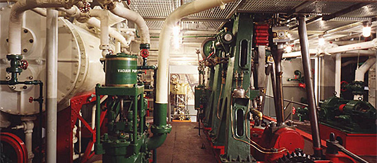
Engineering, Building, and Architecture

Not many museums collect houses. The National Museum of American History has four, as well as two outbuildings, 11 rooms, an elevator, many building components, and some architectural elements from the White House. Drafting manuals are supplemented by many prints of buildings and other architectural subjects. The breadth of the museum's collections adds some surprising objects to these holdings, such as fans, purses, handkerchiefs, T-shirts, and other objects bearing images of buildings.

The engineering artifacts document the history of civil and mechanical engineering in the United States. So far, the Museum has declined to collect dams, skyscrapers, and bridges, but these and other important engineering achievements are preserved through blueprints, drawings, models, photographs, sketches, paintings, technical reports, and field notes.

Text and photograph from Gardner's Photographic Sketchbook of the War, Vol. II. Negative by Barnard & Gibson, text and positive by Alexander Gardner.Early in March, 1862, the rebel army, under Gen.
Description
Text and photograph from Gardner's Photographic Sketchbook of the War, Vol. II. Negative by Barnard & Gibson, text and positive by Alexander Gardner.
Early in March, 1862, the rebel army, under Gen. Johnson, evacuated Centreville and Manassas, (their Northern line,) and commenced a retreat towards Richmond. It was orderly and well conducted for several days, but as the last trains were leaving, some of the soldiers fired a bridge south of the junction, supposing that all the trains had gone. Two, however, had not left, and these were at once fired, together with the surrounding buildings, used by the Railroad Company for depot, machine and repair shops, &c. Everything was destroyed, except half a dozen cars, which contained flour and some camp equipage of a South Carolina Brigade, and which for some reason escaped the conflagration. The old wooden turn-table was uninjured, and is a fair sample of the old fashioned equipage of the Orange and Alexandria Road, at that period. A few mud huts, and about fifty broken down wagons, and the usual debris of a winter's camp, were the sole remnants of the rebel army, which, like the Arabs, had folded its tents, and silently stolen away. Manassas Junction was but a level plain, as seen by the photograph, and with neither natural or artificial works of any strength, the fortifications at that time consisting only of rude mud banks.
Location
Currently not on view
date made
1862-03
maker
Gardner, Alexander
ID Number
1986.0711.0334.09
accession number
1986.0711
catalog number
1986.0711.0334.09
This model was submitted with the application for the patent issued to Thomas B. Dexter, of Lynn, Massachusetts (assignor of one-half his right to the Gilmanton Mills, Belmont, New Hampshire), August 19, 1879, no.
Description
This model was submitted with the application for the patent issued to Thomas B. Dexter, of Lynn, Massachusetts (assignor of one-half his right to the Gilmanton Mills, Belmont, New Hampshire), August 19, 1879, no. 218619.
The model represents a tubular burner with a slightly reduced tip, provided with a vertical diaphragm that divides the burner into two sections. The space on one side of the diaphragm is connected to the oil line and to an air inlet pipe provided with a damper for adjusting the flow of air. The other space is connected to the steam line. In operation the flow of steam from the tip creates suction enough to draw the oil and air through the burner. The oil and air are heated by contact with the diaphragm, which separates them from the steam, and are intimately mixed when they issue from the burner. The diaphragm is notched just inside the tip so that the mixing of the steam and the air and oil results in the formation of a wide, thin, horizontal sheet. This produced a sheet of flame that spread over a large part of the furnace.
Reference:
This description comes from the 1939 Catalog of the Mechanical Collections of the Division of Engineering United States Museum Bulletin 173 by Frank A. Taylor.
Location
Currently not on view
date made
1879
patent date
1879-08-19
inventor
Dexter, Thomas B.
ID Number
MC.308765
catalog number
308765
accession number
89797
patent number
218,619
This model was submitted to the U.S. Patent Office with application for Patent no. 4800, issued October 7, 1846.This engine is very similar to the Perry engine of 1844 (US National Museum accession number 309253).
Description
This model was submitted to the U.S. Patent Office with application for Patent no. 4800, issued October 7, 1846.
This engine is very similar to the Perry engine of 1844 (US National Museum accession number 309253). It differs in that the cylinder is water-jacketed and the hot cooling water is used to heat the fuel retort. Ignition is effected by heated platinum exposed to or separated from the explosive mixture by a valve.
The model shows a horizontal double-acting engine completely water-jacketed. Beside the cylinder is the retort for generating the vapors. Air is mixed with the vapor in a valve box above the retort, and valves operated by cams from a lay shaft admit the explosive mixture to passages leading to the cylinder. The gas is ignited by incandescent platinum, and combustion continues during about one-third of the stroke, the expansion of the products of combustion forcing the piston to the end of the stroke.
To start the engine it was necessary to heat the water about the retort to generate the vapor and to heat the igniter. When running, the engine developed sufficient heat for both purposes.
Perry designed this engine so that the water served not only to cool the cylinder but also to lubricate the piston and piston rod.
Reference:
This description comes from the 1939 Catalog of the Mechanical Collections of the Division of Engineering United States Museum Bulletin 173 by Frank A. Taylor.
Location
Currently not on view
date made
1846
patent date
1846-10-07
inventor
Perry, Stuart
ID Number
ER.251278
accession number
48865
catalog number
251278
patent number
4,800
By 1943, the outlook for an Allied victory in World War II was steadily improving. The reign of the U-boats that had plagued Allied convoys in the Battle of the Atlantic was coming to an end.
Description
By 1943, the outlook for an Allied victory in World War II was steadily improving. The reign of the U-boats that had plagued Allied convoys in the Battle of the Atlantic was coming to an end. And the Axis powers were finally losing the tonnage war, which aimed to sink Allied merchant ships faster than replacements could be built. While the mass-produced Liberty ships were faithfully carrying cargo and troops to war zones, these ships were relatively slow. In response, the War Shipping Administration commissioned a new class of emergency vessels called Victory ships. This model represents one of the 534 Victory ships that were built alongside the Liberty ships in seven shipyards around the country.
Speed was the key difference between the Victory and Liberty ships. When Liberty ships were designed, all of the new steam turbine engines were reserved for naval vessels, leaving the Liberty ships with reciprocating steam engines. While these engines were reliable, the ships could only reach 11 knots, leaving them vulnerable to attack. As the war progressed, more turbine engines became available and were installed in the Victory ships, giving them a speed of over 16 knots.
Another improvement of the Victory design was a stronger and larger hull. This meant that more cargo could be transported at once, and improved the odds of the vessels continuing to serve in the merchant fleet during times of peace. After World War II, 170 Victory ships were sold as commercial freighters. About 20 were loaned back to the military and used in the Korean and Vietnam Wars. Several Victory ships have been preserved as museum ships and are currently located in California and Florida.
date made
early 1940s
commissioned Victory ships like the ones this model represents
War Shipping Administration
ID Number
TR.313023
catalog number
TR*313023
accession number
170015
Crosby Steam Gauge & Valve Co. of Boston, Massachusetts, manufactured this steam engine indicator, serial number 1074D.
Description
Crosby Steam Gauge & Valve Co. of Boston, Massachusetts, manufactured this steam engine indicator, serial number 1074D. It consists of a steel piston; a vented brass cylinder; an external, double wound spring, which can be changed; a large drum with a spiral spring and a single record; and a brass stylus. Accompanying the indicator is a box with twelve springs and some small tools.
An engine indicator is an instrument for graphically recording the pressure versus piston displacement through an engine stroke cycle. Engineers use the resulting diagram to check the design and performance of the engine.
A mechanical indicator consists of a piston, spring, stylus, and recording system. The gas pressure of the cylinder deflects the piston and pushes against the spring, creating a linear relationship between the gas pressure and the deflection of the piston against the spring. The deflection is recorded by the stylus on a rotating drum that is connected to the piston. Most indicators incorporate a mechanical linkage to amplify the movement of the piston to increase the scale of the record.
When the ratio of the frequency of the pressure variation to the natural frequency of the system is small, then the dynamic deflection is equal to the static deflection. To design a system with a high natural frequency, the mass of the piston, spring, stylus, and mechanical linkage must be small, but the stiffness of the spring must be high. The indicator is subjected to high temperatures and pressures and rapid oscillations, imposing a limitation on the reduction in mass. Too stiff a spring will result in a small displacement of the indicator piston and a record too small to measure with accuracy. Multiplication of the displacement will introduce mechanical ad dynamic errors.
The parameters of the problem for designing an accurate and trouble free recorder are such that there is no easy or simple solution. Studying the variety of indicators in the collection shows how different inventors made different compromises in their designs.
Location
Currently not on view
maker
Crosby Steam Gage & Valve Company
ID Number
MC.316797
catalog number
316797
accession number
228496
patent number
1074D
date made
1855
patent date
1855-07-31
inventor
Ericsson, John
ID Number
MC.251279
catalog number
251279
accession number
48865
patent number
13,348
This oiler was submitted to the U.S. Patent Office with the application for the patent issued to Peter D. Hay (assignor to the Michigan Lubricator Co.), of Detroit, Michigan, June 9, 1888, no.
Description
This oiler was submitted to the U.S. Patent Office with the application for the patent issued to Peter D. Hay (assignor to the Michigan Lubricator Co.), of Detroit, Michigan, June 9, 1888, no. 384762.
The model represents a sight-feed oiler in which the oil is contained in a cylindrical glass reservoir and flows by gravity through a needle valve to the bearing into which the oiler is screwed. The needle of the needle valve when closed is held against its seat by a light spring. It is opened by lifting the needle and giving it a short turn so that a pin on the shaft rises out of a slot and rests on the top edge of a brass thumb nut screwed into the central pot of the oiler. This nut may be run up or down on its threads and so determine the amount by which the needle will be raised and held from its seat and so control the rate at which oil is fed from the reservoir. The nut carries a spring-held pin that rests in shallow recesses in the top of the oiler and holds the nut in the position in which it is set and will not permit the nut to be jarred around by the vibration of the machine to which it is attached.
Reference:
This description comes from the 1939 Catalog of the Mechanical Collections of the Division of Engineering United States Museum Bulletin 173 by Frank A. Taylor.
Location
Currently not on view
date made
1888
patent date
1888-06-19
inventor
Hay, Peter D.
ID Number
MC.309248
catalog number
309248
accession number
89797
patent number
384,762
Novelty Iron Works manufactured this McNaught steam engine indicator. It consists of a brass piston and cylinder with a steel spring under the pencil holder.
Description
Novelty Iron Works manufactured this McNaught steam engine indicator. It consists of a brass piston and cylinder with a steel spring under the pencil holder. It takes a direct reading with no linkage on a large drum.
An engine indicator is an instrument for graphically recording the pressure versus piston displacement through an engine stroke cycle. Engineers use the resulting diagram to check the design and performance of the engine.
A mechanical indicator consists of a piston, spring, stylus, and recording system. The gas pressure of the cylinder deflects the piston and pushes against the spring, creating a linear relationship between the gas pressure and the deflection of the piston against the spring. The deflection is recorded by the stylus on a rotating drum that is connected to the piston. Most indicators incorporate a mechanical linkage to amplify the movement of the piston to increase the scale of the record.
When the ratio of the frequency of the pressure variation to the natural frequency of the system is small, then the dynamic deflection is equal to the static deflection. To design a system with a high natural frequency, the mass of the piston, spring, stylus, and mechanical linkage must be small, but the stiffness of the spring must be high. The indicator is subjected to high temperatures and pressures and rapid oscillations, imposing a limitation on the reduction in mass. Too stiff a spring will result in a small displacement of the indicator piston and a record too small to measure with accuracy. Multiplication of the displacement will introduce mechanical ad dynamic errors.
The parameters of the problem for designing an accurate and trouble free recorder are such that there is no easy or simple solution. Studying the variety of indicators in the collection shows how different inventors made different compromises in their designs.
Location
Currently not on view
ID Number
MC.319481
catalog number
319481
accession number
237917
Slip Joint Pliers are for gripping round work, such as pipes and nuts. These pliers are made of steel, have an adjustable grip and yellow plastic covered handles. Made by Fuller Tools. Fuller first started in Whitestone New York in the 1930's.
Description
Slip Joint Pliers are for gripping round work, such as pipes and nuts. These pliers are made of steel, have an adjustable grip and yellow plastic covered handles. Made by Fuller Tools. Fuller first started in Whitestone New York in the 1930's. In 1944 two Canadian brothers, Stanley and Lloyd Davis set up production and made tools near Montreal. In the early 1990's, Fuller moved to Montreal and the US manufacturing facility was consolidated with the Canadian facility. These pliers were used by Jillian Gross while working for Habitat for Humanity, a not-for-profit, non-government organization advocating affordable housing around the world.
When Hurricane Katrina struck the Gulf Coast in August 2005, Jillian Gross had worked with Habitat for Humanity for three years learning woodworking and house-building skills. Groups such as Habitat for Humanity marshaled volunteers, tools and lumber to step in when it became clear that normal avenues of housing assistance were overwhelmed.
In November 2005, Habitat for Humanity launched “America Builds on the National Mall,” a demonstration house-building marathon in Washington, D.C. in which the basic components of 51 homes were assembled within a week and shipped to the Gulf Coast. Upon completion of the project Ms. Gross, one of the house building leaders during this event, donated her tool belt, tools and protective wear to the Smithsonian Institution. The plyers were found in the tool belt.
Location
Currently not on view
ID Number
2005.0276.23
catalog number
2005.0276.23
accession number
2005.0276
This model was submitted to the U.S. Patent Office with application for the patent issued to S. Lloyd Wiegand, of Philadelphia, Pennsylvania, August 6, 1867, no.
Description
This model was submitted to the U.S. Patent Office with application for the patent issued to S. Lloyd Wiegand, of Philadelphia, Pennsylvania, August 6, 1867, no. 67621.
This model is of a boiler having water tubes made up of large tubes closed at the ends with smaller tubes suspended within the large tubes to provide a circulation of steam and water upward in the smaller tubes and of the cooler water down ward in the annular spaces between the larger and smaller tubes. The inventor suggests the use of tubes of different metals to produce a galvanic action for the purpose of preventing deposits of scale within the tubes.
The boiler represented by the model consists of a series of vertical tubes suspended into the furnace from a horizontal header across the top of the boiler setting. The tubes closed at their lower ends, and within each tube is one of smaller diameter. The smaller tubes are suspended from a plate within the header. The headers connecting each row of tubes across the boiler are, in turn, connected by a longitudinal drum above them.
Reference:
This description comes from the 1939 Catalog of the Mechanical Collections of the Division of Engineering United States Museum Bulletin 173 by Frank A. Taylor.
Location
Currently not on view
date made
1867
patent date
1867-08-06
inventor
Wiegand, S. Lloyd
ID Number
MC.309209
catalog number
309209
accession number
89797
patent number
67,621
This manographe, or indicator, was purchased by Professor W. H. Kenerson around 1907.
Description
This manographe, or indicator, was purchased by Professor W. H. Kenerson around 1907. He used it in making tests of the Brayton Oil Engine, National Museum of American History catalog number 313.703, at Brown University.
A pivoted mirror reflects a beam of light to a photosensitive plate or paper. Changes in pressure in the engine cylinder cause the mirror to oscillate up and down; a pin and eccentric actuated by a flexible shaft connected to the engine shaft cause the mirror to oscillate from side to side.
The indicator is housed in a wooden box that is 5 inches by 6 inches by 14 inches, with a brass pipe fitting and gear box at one end. The opposite end is open to receive a plate holder of a ground glass. A T-shaped tube lets light into one side, and an adjustable prism inside directs the light to the mirror. The flexible shaft is 32 inches long and covered with black fabric. Four plate holders, one ground glass, a steel petcock and a tapered hollow steel plug are included with the instrument. It is marked “Manographe Hospitalier-Carpentier, Brevete, S G D G, J. Carpentier, Paris.”
An engine indicator is an instrument for graphically recording the pressure versus piston displacement through an engine stroke cycle. Engineers use the resulting diagram to check the design and performance of the engine.
A mechanical indicator consists of a piston, spring, stylus, and recording system. The gas pressure of the cylinder deflects the piston and pushes against the spring, creating a linear relationship between the gas pressure and the deflection of the piston against the spring. The deflection is recorded by the stylus on a rotating drum that is connected to the piston. Most indicators incorporate a mechanical linkage to amplify the movement of the piston to increase the scale of the record.
When the ratio of the frequency of the pressure variation to the natural frequency of the system is small, then the dynamic deflection is equal to the static deflection. To design a system with a high natural frequency, the mass of the piston, spring, stylus, and mechanical linkage must be small, but the stiffness of the spring must be high. The indicator is subjected to high temperatures and pressures and rapid oscillations, imposing a limitation on the reduction in mass. Too stiff a spring will result in a small displacement of the indicator piston and a record too small to measure with accuracy. Multiplication of the displacement will introduce mechanical ad dynamic errors.
The parameters of the problem for designing an accurate and trouble free recorder are such that there is no easy or simple solution. Studying the variety of indicators in the collection shows how different inventors made different compromises in their designs.
Location
Currently not on view
ID Number
MC.313704
catalog number
313704
accession number
192776
This model was submitted to the U.S. Patent Office with the application for Patent no. 111088, issued to Alexander K. Rider, of New York, New York, January 17, 1871, reissued August 24, 188-, no.
Description
This model was submitted to the U.S. Patent Office with the application for Patent no. 111088, issued to Alexander K. Rider, of New York, New York, January 17, 1871, reissued August 24, 188-, no. 9353.
This engine consists of a power piston and a transfer piston so connected with valves and passages that the cold air is received and compressed in the same cylinder in which the hot air performs its work. Its simple construction is an improvement on the John Ericsson hot-air engines of 1855-1858.
A vertical cylinder contains two independent pistons with suitable valves that permit cold air to be drawn into the cylinder, compressed, circulated between heated furnace walls, expanded under a power piston and then exhausted. The upper piston is equipped with two spring-closed intake valves that open on the upstroke of the piston allowing air to fill the cylinder between the upper and lower pistons. This air is then compressed on the downstroke of the upper piston until the pressure is sufficient to open a valve in a passage leading to a heated space surrounding the furnace. The heated and compressed air then passes into the cylinder below the lower piston where it expands, performing work against the piston.
Reference:
This description comes from the 1939 Catalog of the Mechanical Collections of the Division of Engineering United States Museum Bulletin 173 by Frank A. Taylor.
Location
Currently not on view
date made
1871
patent date
1871-01-17
inventor
Rider, Alexander K.
ID Number
ER.308714
accession number
89797
catalog number
308714
patent number
111,088
Crosby Steam Gauge & Valve Co. of Boston, Massachusetts, manufactured this steam engine indicator, serial number 3309. It consists of a piston, which is stuck inside the cylinder. A brass stylus can record onto a large small drum with a spiral spring and a single record.
Description
Crosby Steam Gauge & Valve Co. of Boston, Massachusetts, manufactured this steam engine indicator, serial number 3309. It consists of a piston, which is stuck inside the cylinder. A brass stylus can record onto a large small drum with a spiral spring and a single record. Accompanying the indicator is a box with twelve springs and a spring wrench.
An engine indicator is an instrument for graphically recording the pressure versus piston displacement through an engine stroke cycle. Engineers use the resulting diagram to check the design and performance of the engine.
A mechanical indicator consists of a piston, spring, stylus, and recording system. The gas pressure of the cylinder deflects the piston and pushes against the spring, creating a linear relationship between the gas pressure and the deflection of the piston against the spring. The deflection is recorded by the stylus on a rotating drum that is connected to the piston. Most indicators incorporate a mechanical linkage to amplify the movement of the piston to increase the scale of the record.
When the ratio of the frequency of the pressure variation to the natural frequency of the system is small, then the dynamic deflection is equal to the static deflection. To design a system with a high natural frequency, the mass of the piston, spring, stylus, and mechanical linkage must be small, but the stiffness of the spring must be high. The indicator is subjected to high temperatures and pressures and rapid oscillations, imposing a limitation on the reduction in mass. Too stiff a spring will result in a small displacement of the indicator piston and a record too small to measure with accuracy. Multiplication of the displacement will introduce mechanical ad dynamic errors.
The parameters of the problem for designing an accurate and trouble free recorder are such that there is no easy or simple solution. Studying the variety of indicators in the collection shows how different inventors made different compromises in their designs.
Location
Currently not on view
maker
Crosby Steam Gage & Valve Company
ID Number
MC.316795
catalog number
316795
accession number
228496
This model was submitted to the U.S. Patent Office with the application for the patent issued to George H. Corliss, of Providence, Rhode Island, May 27, 1879, no.
Description
This model was submitted to the U.S. Patent Office with the application for the patent issued to George H. Corliss, of Providence, Rhode Island, May 27, 1879, no. 215798.
The model represents a bank of curved water tubes joined in vertical rows by the separate cases or tube ends, which are the subject of the patent. Each end of each tube is threaded into the side of the cylindrical casting, which is provided with machined surfaces that allow the separate castings to go together tightly to form a continuous tube sheet or header for each vertical row of tubes. The castings forming each header are held together by a single long bolt, which threads into a casting that forms a common connector along the lower ends of the vertical headers.
Reference:
This description comes from the 1939 Catalog of the Mechanical Collections of the Division of Engineering United States Museum Bulletin 173 by Frank A. Taylor.
Location
Currently not on view
date made
1879
patent date
1879-05-27
inventor
Corliss, George H.
ID Number
MC.309214
catalog number
309214
accession number
89797
patent number
215,798
This pencil was grouped with a number of pencils found in the pocket of a tool belt used by Jillian Gross while working for Habitat for Humanity, a not-for-profit, non-government organization advocating affordable housing around the world.
Description
This pencil was grouped with a number of pencils found in the pocket of a tool belt used by Jillian Gross while working for Habitat for Humanity, a not-for-profit, non-government organization advocating affordable housing around the world. Carpenter pencils have two wide, flat sides to keep them from rolling. The graphite core is generally wide and flat, making it easy to mark course materials when using the flat side while using the thinner side for precision marks.
When Hurricane Katrina struck the Gulf Coast in August 2005, Jillian Gross had worked with Habitat for Humanity for three years learning woodworking and house-building skills. Groups such as Habitat for Humanity marshaled volunteers, tools and lumber to step in when it became clear that normal avenues of housing assistance were overwhelmed.
In November 2005, Habitat for Humanity launched “America Builds on the National Mall,” a demonstration house-building marathon in Washington, D.C. in which the basic components of 51 homes were assembled within a week and shipped to the Gulf Coast. Upon completion of the project Ms. Gross, one of the house building leaders during this event, donated her tool belt, tools and protective wear to the Smithsonian Institution.
Location
Currently not on view
ID Number
2005.0276.27
catalog number
2005.0276.27
accession number
2005.0276
The glazier knife has multiple uses: scraping, roller squeegee, spackle spreader, crack or crevice cleaner and can opener. Made by Warner Manufacturing Company, Plymouth, Minnesota, makers of hand and edge tools and light equipment.
Description
The glazier knife has multiple uses: scraping, roller squeegee, spackle spreader, crack or crevice cleaner and can opener. Made by Warner Manufacturing Company, Plymouth, Minnesota, makers of hand and edge tools and light equipment. It was used by Jillian Gross while working for Habitat for Humanity, a not-for-profit, non-government organization advocating affordable housing around the world.
When Hurricane Katrina struck the Gulf Coast in August 2005, Jillian Gross had worked with Habitat for Humanity for three years learning woodworking and house-building skills. Groups such as Habitat for Humanity marshaled volunteers, tools and lumber to step in when it became clear that normal avenues of housing assistance were overwhelmed.
In November 2005, Habitat for Humanity launched “America Builds on the National Mall,” a demonstration house-building marathon in Washington, D.C. in which the basic components of 51 homes were assembled within a week and shipped to the Gulf Coast. Upon completion of the project Ms. Gross, one of the house building leaders during this event, donated her tool belt, tools and protective wear to the Smithsonian Institution. The glazier knife was kept in the pocket of a tool belt.
Location
Currently not on view
ID Number
2005.0276.25
catalog number
2005.0276.25
accession number
2005.0276
A utility knife is a general purpose cutting tool. This knife has a retractable steel blade and a red painted aluminum holder. It was made in China for the American home improvement store Lowe's Task Force brand.
Description
A utility knife is a general purpose cutting tool. This knife has a retractable steel blade and a red painted aluminum holder. It was made in China for the American home improvement store Lowe's Task Force brand. The manufacturering company that produces their tools can vary from year to year. The knife was used by Jillian Gross while working for Habitat for Humanity, a not-for-profit, non-government organization advocating affordable housing around the world.
When Hurricane Katrina struck the Gulf Coast in August 2005, Jillian Gross had worked with Habitat for Humanity for three years learning woodworking and house-building skills. Groups such as Habitat for Humanity marshaled volunteers, tools and lumber to step in when it became clear that normal avenues of housing assistance were overwhelmed.
In November 2005, Habitat for Humanity launched “America Builds on the National Mall,” a demonstration house-building marathon in Washington, D.C. in which the basic components of 51 homes were assembled within a week and shipped to the Gulf Coast. Upon completion of the project Ms. Gross, one of the house building leaders during this event, donated her tool belt, tools and protective wear to the Smithsonian Institution. The notebook was kept in the pocket of a tool belt.
Location
Currently not on view
ID Number
2005.0276.21
catalog number
2005.0276.21
accession number
2005.0276
This pen was used by Jillian Gross while working for Habitat for Humanity, a not-for-profit, non-government organization advocating affordable housing around the world.
Description
This pen was used by Jillian Gross while working for Habitat for Humanity, a not-for-profit, non-government organization advocating affordable housing around the world. This red transparent plastic pen has a rubber grip, retractable point and pocket clip.
When Hurricane Katrina struck the Gulf Coast in August 2005, Jillian Gross had worked with Habitat for Humanity for three years learning woodworking and house-building skills. Groups such as Habitat for Humanity marshaled volunteers, tools and lumber to step in when it became clear that normal avenues of housing assistance were overwhelmed.
In November 2005, Habitat for Humanity launched “America Builds on the National Mall,” a demonstration house-building marathon in Washington, D.C. in which the basic components of 51 homes were assembled within a week and shipped to the Gulf Coast. Upon completion of the project Ms. Gross, one of the house building leaders during this event, donated her tool belt, tools and protective wear to the Smithsonian Institution. The pen was kept with her notebook.
Location
Currently not on view
ID Number
2005.0276.36
catalog number
2005.0276.36
accession number
2005.0276
This general purpose or common hammer is used for pounding nails and prying nails or other light material such as molding. The hammer is all one forged steel piece with a blue nylon grip. It has a smooth striking face and straight claw.
Description
This general purpose or common hammer is used for pounding nails and prying nails or other light material such as molding. The hammer is all one forged steel piece with a blue nylon grip. It has a smooth striking face and straight claw. It was used by Jillian Gross while working for Habitat for Humanity, a not-for-profit, non-government organization advocating affordable housing around the world.
When Hurricane Katrina struck the Gulf Coast in August 2005, Jillian Gross had worked with Habitat for Humanity for three years learning woodworking and house-building skills. Groups such as Habitat for Humanity marshaled volunteers, tools and lumber to step in when it became clear that normal avenues of housing assistance were overwhelmed.
In November 2005, Habitat for Humanity launched “America Builds on the National Mall,” a demonstration house-building marathon in Washington, D.C. in which the basic components of 51 homes were assembled within a week and trucked off to the Gulf Coast. Upon completion of the project Ms. Gross, one of the house building leaders during this event, donated her tool belt, tools and protective wear to the Smithsonian Institution.
Location
Currently not on view
maker
Estwing
ID Number
2005.0276.10
catalog number
2005.0276.10
accession number
2005.0276
This nail puller, also referred to as a cat's paw, is designed to pull out nails and for light demolition. The length has a hexagonal shape, each end is curved, tapered and slotted.
Description
This nail puller, also referred to as a cat's paw, is designed to pull out nails and for light demolition. The length has a hexagonal shape, each end is curved, tapered and slotted. It was used by Jillian Gross while working for Habitat for Humanity, a not-for-profit, non-government organization advocating affordable housing around the world.
When Hurricane Katrina struck the Gulf Coast in August 2005, Jillian Gross had worked with Habitat for Humanity for three years learning woodworking and house-building skills. Groups such as Habitat for Humanity marshaled volunteers, tools and lumber to step in when it became clear that normal avenues of housing assistance were overwhelmed.
In November 2005, Habitat for Humanity launched “America Builds on the National Mall,” a demonstration house-building marathon in Washington, D.C. in which the basic components of 51 homes were assembled within a week and shipped to the Gulf Coast. Upon completion of the project Ms. Gross, one of the house building leaders during this event, donated her tool belt, tools and protective wear to the Smithsonian Institution.
Location
Currently not on view
ID Number
2005.0276.12
catalog number
2005.0276.12
accession number
2005.0276
This short flat pry bar is for pulling nails and performing light work such as prying paneling or molding. Both ends are curved and slotted.
Description
This short flat pry bar is for pulling nails and performing light work such as prying paneling or molding. Both ends are curved and slotted. It was used by Jillian Gross while working for Habitat for Humanity, a not-for-profit, non-government organization advocating affordable housing around the world.
When Hurricane Katrina struck the Gulf Coast in August 2005, Jillian Gross had worked with Habitat for Humanity for three years learning woodworking and house-building skills. Groups such as Habitat for Humanity marshaled volunteers, tools and lumber to step in when it became clear that normal avenues of housing assistance were overwhelmed.
In November 2005, Habitat for Humanity launched “America Builds on the National Mall,” a demonstration house-building marathon in Washington, D.C. in which the basic components of 51 homes were assembled within a week and shipped to the Gulf Coast. Upon completion of the project Ms. Gross, one of the house building leaders during this event, donated her tool belt, tools and protective wear to the Smithsonian Institution.
Location
Currently not on view
ID Number
2005.0276.19
catalog number
2005.0276.19
accession number
2005.0276
This belt clip was distributed in a Swanson speed square package. The clip hooks on to a belt and holds a speed square or other tools.
Description
This belt clip was distributed in a Swanson speed square package. The clip hooks on to a belt and holds a speed square or other tools. It was used by Jillian Gross while working for Habitat for Humanity, a not-for-profit, non-government organization advocating affordable housing around the world.
When Hurricane Katrina struck the Gulf Coast in August 2005, Jillian Gross had worked with Habitat for Humanity for three years learning woodworking and house-building skills. Groups such as Habitat for Humanity marshaled volunteers, tools and lumber to step in when it became clear that normal avenues of housing assistance were overwhelmed.
In November 2005, Habitat for Humanity launched “America Builds on the National Mall,” a demonstration house-building marathon in Washington, D.C. in which the basic components of 51 homes were assembled within a week and shipped to the Gulf Coast. Upon completion of the project Ms. Gross, one of the house building leaders during this event, donated her tool belt, tools and protective wear to the Smithsonian Institution.
Location
Currently not on view
ID Number
2005.0276.17
catalog number
2005.0276.17
accession number
2005.0276
This short, flat pry bar is for pulling nails and performing light work such as prying paneling or molding. Both ends are curved and slotted.
Description
This short, flat pry bar is for pulling nails and performing light work such as prying paneling or molding. Both ends are curved and slotted. It was used by Jillian Gross while working for Habitat for Humanity, a not-for-profit, non-government organization advocating affordable housing around the world.
When Hurricane Katrina struck the Gulf Coast in August 2005, Jillian Gross had worked with Habitat for Humanity for three years learning woodworking and house-building skills. Groups such as Habitat for Humanity marshaled volunteers, tools and lumber to step in when it became clear that normal avenues of housing assistance were overwhelmed.
In November 2005, Habitat for Humanity launched “America Builds on the National Mall,” a demonstration house-building marathon in Washington, D.C. in which the basic components of 51 homes were assembled within a week and shipped to the Gulf Coast. Upon completion of the project Ms. Gross, one of the house building leaders during this event, donated her tool belt, tools and protective wear to the Smithsonian Institution.
Location
Currently not on view
ID Number
2005.0276.18
catalog number
2005.0276.18
accession number
2005.0276
This model was submitted to the U.S. Patent Office with the application for the patent issued to Charles Miller, of Belleville, Illinois, May 3, 1859, no. 23852.The engine has two oval pistons or cams each running in a separate circular cylinder or casing.
Description
This model was submitted to the U.S. Patent Office with the application for the patent issued to Charles Miller, of Belleville, Illinois, May 3, 1859, no. 23852.
The engine has two oval pistons or cams each running in a separate circular cylinder or casing. Sliding abutments in the casing bearing on the edges of the cams direct the steam in the forward direction around the casing. Admission of steam is controlled by two flat slide valves working in steam chests on top of the casing. The valves are operated by two eccentrics on the engine shaft. The engine is reversible.
Reference:
This description comes from the 1939 Catalog of the Mechanical Collections of the Division of Engineering United States Museum Bulletin 173 by Frank A. Taylor.
Location
Currently not on view
date made
1859
patent date
1859-05-03
inventor
Miller, Charles
ID Number
ER.251294
accession number
48865
catalog number
251294
patent number
23,852

Our collection database is a work in progress. We may update this record based on further research and review. Learn more about our approach to sharing our collection online.

If you would like to know how you can use content on this page, see the Smithsonian's Terms of Use. If you need to request an image for publication or other use, please visit Rights and Reproductions.