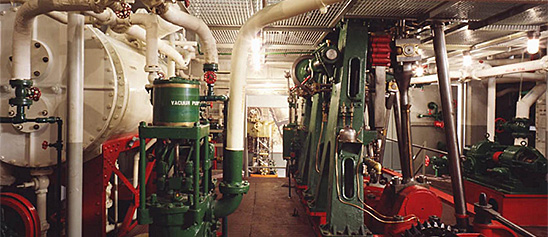
Engineering, Building, and Architecture

Not many museums collect houses. The National Museum of American History has four, as well as two outbuildings, 11 rooms, an elevator, many building components, and some architectural elements from the White House. Drafting manuals are supplemented by many prints of buildings and other architectural subjects. The breadth of the museum's collections adds some surprising objects to these holdings, such as fans, purses, handkerchiefs, T-shirts, and other objects bearing images of buildings.

The engineering artifacts document the history of civil and mechanical engineering in the United States. So far, the Museum has declined to collect dams, skyscrapers, and bridges, but these and other important engineering achievements are preserved through blueprints, drawings, models, photographs, sketches, paintings, technical reports, and field notes.

This toy steam engine was manufactured by an unknown maker during the early 20th century. The engine has a reversible slide valve and flywheel, with a horizontal brass boiler.Live steam toys enjoyed a period of popularity from the 1880s until the 1930s.
Description (Brief)
This toy steam engine was manufactured by an unknown maker during the early 20th century. The engine has a reversible slide valve and flywheel, with a horizontal brass boiler.
Live steam toys enjoyed a period of popularity from the 1880s until the 1930s. The miniature steam engines were marketed as both toys and instructive devices that mimicked full-scale steam-powered machines and allowed every boy and girl to be their own engineer. In toy steam engines, a heating source is introduced into the firebox below the boiler (early toys used lit wicks fueled by denatured alcohol, later toys used electricity) which heated the water to produce the steam pressure that ran the engine. A variety of accessories could be powered by the engine; attachments included windmills, pumps, grinders, and electric lights.
Location
Currently not on view
date made
early 20th century
ID Number
MC.329014
catalog number
329014
accession number
278175
The Time-O-Stat Controls Corporation of Elkhart, Indiana produced this Time-O-Stat thermostat around 1930. Time-O-Stat was a large company that specialized in control systems that had applications in a variety of industrial, commercial, and domestic applications.
Description
The Time-O-Stat Controls Corporation of Elkhart, Indiana produced this Time-O-Stat thermostat around 1930. Time-O-Stat was a large company that specialized in control systems that had applications in a variety of industrial, commercial, and domestic applications. Time-O-Stat was purchased by the Minneapolis-Honeywell Regulator Company in 1934, who continued to sell a Time-O-Stat brand thermostat in the years following the acquisition and used Time-O-Stat control patents in future devices.
The ubiquity of thermostats in 21st century homes shrouds the decades of innovation, industrial design, and engineering that went into making them an everyday object in almost every home. In the early 20th century, a majority of American households still heated their homes with manually operated furnaces that required a trip down to the basement and stoking the coal fired furnace. Albert Butz’s “damper-flapper” system was patented in 1886 and allowed home owner to set the thermostat to a certain temperature which would open a damper to the furnace, increasing the fire and heating the house. Progressive innovations allowed for the thermostats to use gas lines, incorporate electricity, turn on at a set time, include heating and cooling in one mechanism, and even connect to the internet.
ID Number
2008.0011.13
accession number
2008.0011
catalog number
2008.0011.13
In places that required many clocks—factories, office and public buildings, or schools—time was often distributed by a system of "master" and "slave" clocks.
Description
In places that required many clocks—factories, office and public buildings, or schools—time was often distributed by a system of "master" and "slave" clocks. In such a system, a central timekeeper, the master clock, sent periodic impulses, usually electric or pneumatic, to any number of secondary or slave clocks. These slave clocks could be located anywhere, without regard for convenience of winding, because they needed none. The master clock could also drive other time signals like classroom bells, factory whistles, or time stamps. More economical to install and more convenient to maintain than an equal number of independent clocks, the system also ensured that all dials within the system agreed.
The museum collection contains such a timekeeping system. The system's master clock (Cat. 310,569), built by E. Howard and Company of Boston, is a mechanical tower clock movement equipped with electrical contacts. Once a minute the escapement, through a pair of rotary switches, closes an electrical circuit and sends an impulse to the slave dial (Cat. 310,570), where electromagnets advance the hands. Batteries at the base of the master clock supply current.
This clock and dial were components of a system that served the Smithsonian between about 1881 and 1932. First housed in the north tower of the Arts and Industries Building, the clock movement distributed impulses to eighteen dials in that building and the Castle, the Smithsonian's earliest building. Tunnels under the floors carried the wiring. The clock room also housed a telephone switchboard, a watchman's clock, a central burglar alarm, and call bells—all of which, like the time distribution system, relied on the newly harnessed power of electricity. "Indeed," boasted the Smithsonian's annual report for 1881, "it is believed that in no building in the world, with the exception of the Grand Opera House in Paris, is there so perfect and complete an application of electricity to practical services."
Date made
1880
manufacturer
E. Howard & Co.
ID Number
ME.310569
catalog number
310569
accession number
123081
This model was submitted to the U.S. Patent Office with the application for the patent issued to H. Uhry and H. A. Luttgens, of Paterson, New Jersey, March 20, 1855, no. 12564.The model represents a “link motion” applicable to marine, locomotive, or stationary steam engine.
Description
This model was submitted to the U.S. Patent Office with the application for the patent issued to H. Uhry and H. A. Luttgens, of Paterson, New Jersey, March 20, 1855, no. 12564.
The model represents a “link motion” applicable to marine, locomotive, or stationary steam engine. It is a combination of three eccentrics, the ordinary Stephenson link motion, an additional link pivoted to the Stephenson link, a differential rocker, and a main rocker. The main rocker and the Stephenson link operate one valve, which distributes steam to the cylinder, supplies outside lead, and cuts off the steam in proportion to the decrease of travel. The valve operated by the differential rocker exhausts the steam and opens and cuts off the admission of steam near full stroke of the piston.
Reference:
This description comes from the 1939 Catalog of the Mechanical Collections of the Division of Engineering United States Museum Bulletin 173 by Frank A. Taylor.
Location
Currently not on view
date made
1855
patent date
1855-03-20
inventor
Uhry, H.
ID Number
MC.308656
catalog number
308656
accession number
89797
patent number
12,564
This is a double end pry bar designed to pull out nails and for light demolition. The length has a flat shape, one end has a slight curve that is tapered and slotted and the other end is shaped like the claw portion of a common hammer.
Description
This is a double end pry bar designed to pull out nails and for light demolition. The length has a flat shape, one end has a slight curve that is tapered and slotted and the other end is shaped like the claw portion of a common hammer. It was used by Jillian Gross while working for Habitat for Humanity, a not-for-profit, non-government organization advocating affordable housing around the world.
When Hurricane Katrina struck the Gulf Coast in August 2005, Jillian Gross had worked with Habitat for Humanity for three years learning woodworking and house-building skills. Groups such as Habitat for Humanity marshaled volunteers, tools and lumber to step in when it became clear that normal avenues of housing assistance were overwhelmed.
In November 2005, Habitat for Humanity launched “America Builds on the National Mall,” a demonstration house-building marathon in Washington, D.C. in which the basic components of 51 homes were assembled within a week and shipped to the Gulf Coast. Upon completion of the project Ms. Gross, one of the house building leaders during this event, donated her tool belt, tools and protective wear to the Smithsonian Institution.
Location
Currently not on view
date made
1998-2005
ID Number
2005.0276.11
catalog number
2005.0276.11
accession number
2005.0276
Chisels are used to cut and shape wood, stone and other hard materials. A paring chisel is a common woodworking tool which is used to cut and shave off thin amounds of wood. This chisel has a yellow tansparent handle and a 1" wide steel cutting edge or blade.
Description
Chisels are used to cut and shape wood, stone and other hard materials. A paring chisel is a common woodworking tool which is used to cut and shave off thin amounds of wood. This chisel has a yellow tansparent handle and a 1" wide steel cutting edge or blade. It was used by Jillian Gross while working for Habitat for Humanity, a not-for-profit, non-government organization advocating affordable housing around the world.
When Hurricane Katrina struck the Gulf Coast in August 2005, Jillian Gross had worked with Habitat for Humanity for three years learning woodworking and house-building skills. Groups such as Habitat for Humanity marshaled volunteers, tools and lumber to step in when it became clear that normal avenues of housing assistance were overwhelmed.
In November 2005, Habitat for Humanity launched “America Builds on the National Mall,” a demonstration house-building marathon in Washington, D.C. in which the basic components of 51 homes were assembled within a week and shipped to the Gulf Coast. Upon completion of the project Ms. Gross, one of the house building leaders during this event, donated her tool belt, tools and protective wear to the Smithsonian Institution.
Location
Currently not on view
ID Number
2005.0276.20
catalog number
2005.0276.20
accession number
2005.0276
This Peerless brand toy steam engines was manufactured around 1900. The overtype engine consists of a horizontal boiler with sight glass and lever safety valve. A slide valve engine powers a flywheel on top of the boiler. The engine sits on an iron frame.Currently not on view
Description (Brief)
This Peerless brand toy steam engines was manufactured around 1900. The overtype engine consists of a horizontal boiler with sight glass and lever safety valve. A slide valve engine powers a flywheel on top of the boiler. The engine sits on an iron frame.
Location
Currently not on view
date made
ca 1900
ID Number
MC.329001
catalog number
329001
accession number
278175
Small, flat head screwdriver, red plastic handle with the name Kobalt on its side. Kobalt is a house brand sold exclusively at the American home improvement store Lowe's.
Description
Small, flat head screwdriver, red plastic handle with the name Kobalt on its side. Kobalt is a house brand sold exclusively at the American home improvement store Lowe's. The screwdriver was used by Jillian Gross while working for Habitat for Humanity, a not-for-profit, non-government organization advocating affordable housing around the world.
When Hurricane Katrina struck the Gulf Coast in August 2005, Jillian Gross had worked with Habitat for Humanity for three years learning woodworking and house-building skills. Groups such as Habitat for Humanity marshaled volunteers, tools and lumber to step in when it became clear that normal avenues of housing assistance were overwhelmed.
In November 2005, Habitat for Humanity launched “America Builds on the National Mall,” a demonstration house-building marathon in Washington, D.C. in which the basic components of 51 homes were assembled within a week and shipped to the Gulf Coast. Upon completion of the project Ms. Gross, one of the house building leaders during this event, donated her tool belt, tools and protective wear to the Smithsonian Institution.
Location
Currently not on view
ID Number
2005.0276.22
catalog number
2005.0276.22
accession number
2005.0276
Ashcroft Mfg. Co. of Bridgeport, Connecticut, manufactured this Tabor steam engine indicator, serial number 2325.
Description
Ashcroft Mfg. Co. of Bridgeport, Connecticut, manufactured this Tabor steam engine indicator, serial number 2325. It consists of a brass piston with three grooves; a vented brass cylinder; an internal, single wound spring, which can be changed; a large drum with a coil spring and a single record. The end of the linkage that holds the stylus is missing, as is the pulley. Accompanying the indicator is a box with several springs.
An engine indicator is an instrument for graphically recording the pressure versus piston displacement through an engine stroke cycle. Engineers use the resulting diagram to check the design and performance of the engine.
A mechanical indicator consists of a piston, spring, stylus, and recording system. The gas pressure of the cylinder deflects the piston and pushes against the spring, creating a linear relationship between the gas pressure and the deflection of the piston against the spring. The deflection is recorded by the stylus on a rotating drum that is connected to the piston. Most indicators incorporate a mechanical linkage to amplify the movement of the piston to increase the scale of the record.
When the ratio of the frequency of the pressure variation to the natural frequency of the system is small, then the dynamic deflection is equal to the static deflection. To design a system with a high natural frequency, the mass of the piston, spring, stylus, and mechanical linkage must be small, but the stiffness of the spring must be high. The indicator is subjected to high temperatures and pressures and rapid oscillations, imposing a limitation on the reduction in mass. Too stiff a spring will result in a small displacement of the indicator piston and a record too small to measure with accuracy. Multiplication of the displacement will introduce mechanical ad dynamic errors.
The parameters of the problem for designing an accurate and trouble free recorder are such that there is no easy or simple solution. Studying the variety of indicators in the collection shows how different inventors made different compromises in their designs.
Location
Currently not on view
maker
Ashcroft Mfg. Co.
ID Number
MC.316791
catalog number
316791
accession number
228496
The Minneapolis-Honeywell Regulator Company manufactured this Honeywell T852 electric clock thermostat beginning in 1960. The thermostat had two external tabs for setting the temperature for daytime and nighttime.
Description
The Minneapolis-Honeywell Regulator Company manufactured this Honeywell T852 electric clock thermostat beginning in 1960. The thermostat had two external tabs for setting the temperature for daytime and nighttime. The thermostat connected to the house’s electric system so that it did not have to be wound or set.
The ubiquity of thermostats in 21st century homes shrouds the decades of innovation, industrial design, and engineering that went into making them an everyday object in almost every home. In the early 20th century, a majority of American households still heated their homes with manually operated furnaces that required a trip down to the basement and stoking the coal fired furnace. Albert Butz’s “damper-flapper” system was patented in 1886 and allowed home owner to set the thermostat to a certain temperature which would open a damper to the furnace, increasing the fire and heating the house. Progressive innovations allowed for the thermostats to use gas lines, incorporate electricity, turn on at a set time, include heating and cooling in one mechanism, and even connect to the internet.
Location
Currently not on view
date made
1960
ID Number
2008.0011.10
accession number
2008.0011
catalog number
2008.0011.10
This model was submitted to the U.S. Patent Office with the application for the patent issued to Horatio Allen, of New York, New York, August 29, 1848, no.
Description
This model was submitted to the U.S. Patent Office with the application for the patent issued to Horatio Allen, of New York, New York, August 29, 1848, no. 5745.
This is an adjustable drop cut-off valve gear in which a poppet valve is raised by a lift rod but is permitted to return to its seat sooner or more rapidly than the lift rod returns.
The model represents a poppet steam valve raised from its seat by an arm fixed at right angles to a lift rod, which works vertically and parallel to the valve stem. Upon the face of the arm is a moveable block a part of the upper surface of which is parallel to the face of the arm and a part of which is a steep curve. All the movement of the valve is transmitted to it through a roller on its stem, which rolls on the surface of this block. The block is so linked with a vibratory rod, which receives its motion from the cross head of the engine, that the block will move along the face of the lift rod arm and bring different points of its surface under the roller of the valve stem. By proper adjustment the roller will rest upon the flat part of the block and move with the lift rod as it is rising and the valve is opening, then the block moves so that the roller comes to the edge of the inclined portion and rolls down the incline permitting the valve to drop more quickly than the lift rod. The movement of the block on the arm and consequently the point of cut-off are fully adjustable.
Reference:
This description comes from the 1939 Catalog of the Mechanical Collections of the Division of Engineering United States Museum Bulletin 173 by Frank A. Taylor.
Location
Currently not on view
date made
1848
patent date
1848-08-29
ID Number
MC.308643
catalog number
308643
accession number
89797
patent number
5,745
This horizontal model steam engine was manufactured by an unknown maker in the early 20th century. The engine has a slide valve and 7.5-inch flywheel.Currently not on view
Description (Brief)
This horizontal model steam engine was manufactured by an unknown maker in the early 20th century. The engine has a slide valve and 7.5-inch flywheel.
Location
Currently not on view
ID Number
MC.329023
catalog number
329023
accession number
278175
This model was submitted to the U.S. Patent Office with the application for the patent issued to Horatio Allen, of New York, New York, April 30, 1842, no.
Description
This model was submitted to the U.S. Patent Office with the application for the patent issued to Horatio Allen, of New York, New York, April 30, 1842, no. 2597.
This model represents a valve gear in which separate steam chests are employed for the head-end and crank-end main steam valves. The supply of steam to each of these steam chests is controlled by additional cut-off valves, the movement of which is adjustable. The inventor refers to this invention as an improvement in the valve gear patented by him August 21, 1841 (patent number 2227).
The model shows a portion of the cylinder of a horizontal engine with only the piston rod and cross head represented. A steam chest in which are located the ports leading to the inner or main steam chests is shown in section, revealing the cut-off valves on their seats. These cut-off valves are plain flat plates connected to opposite ends of a beam, which receives a vibratory motion from the cross head of the engine. The beam and its rock shaft are picoted in a lever by which the pivot can be moved and the time of cut-of varied. This the inventor calls “cut-off with movable rock shaft.” He suggests that a similar result can be obtained by constructing the cut-off ports in a movable plate which he calls “cut-off with single adjustable seat.”
Reference:
This description comes from the 1939 Catalog of the Mechanical Collections of the Division of Engineering United States Museum Bulletin 173 by Frank A. Taylor.
Location
Currently not on view
date made
1842
patent date
1842-04-30
inventor
Allen, Horatio
ID Number
MC.308640
catalog number
308640
accession number
89797
patent number
2,597
Text and photograph from Gardner's Photographic Sketchbook of the War, Vol. II. Negative by Barnard & Gibson, text and positive by Alexander Gardner.Early in March, 1862, the rebel army, under Gen.
Description
Text and photograph from Gardner's Photographic Sketchbook of the War, Vol. II. Negative by Barnard & Gibson, text and positive by Alexander Gardner.
Early in March, 1862, the rebel army, under Gen. Johnson, evacuated Centreville and Manassas, (their Northern line,) and commenced a retreat towards Richmond. It was orderly and well conducted for several days, but as the last trains were leaving, some of the soldiers fired a bridge south of the junction, supposing that all the trains had gone. Two, however, had not left, and these were at once fired, together with the surrounding buildings, used by the Railroad Company for depot, machine and repair shops, &c. Everything was destroyed, except half a dozen cars, which contained flour and some camp equipage of a South Carolina Brigade, and which for some reason escaped the conflagration. The old wooden turn-table was uninjured, and is a fair sample of the old fashioned equipage of the Orange and Alexandria Road, at that period. A few mud huts, and about fifty broken down wagons, and the usual debris of a winter's camp, were the sole remnants of the rebel army, which, like the Arabs, had folded its tents, and silently stolen away. Manassas Junction was but a level plain, as seen by the photograph, and with neither natural or artificial works of any strength, the fortifications at that time consisting only of rude mud banks.
Location
Currently not on view
date made
1862-03
maker
Gardner, Alexander
ID Number
1986.0711.0334.09
accession number
1986.0711
catalog number
1986.0711.0334.09
This model was submitted with the application for the patent issued to Thomas B. Dexter, of Lynn, Massachusetts (assignor of one-half his right to the Gilmanton Mills, Belmont, New Hampshire), August 19, 1879, no.
Description
This model was submitted with the application for the patent issued to Thomas B. Dexter, of Lynn, Massachusetts (assignor of one-half his right to the Gilmanton Mills, Belmont, New Hampshire), August 19, 1879, no. 218619.
The model represents a tubular burner with a slightly reduced tip, provided with a vertical diaphragm that divides the burner into two sections. The space on one side of the diaphragm is connected to the oil line and to an air inlet pipe provided with a damper for adjusting the flow of air. The other space is connected to the steam line. In operation the flow of steam from the tip creates suction enough to draw the oil and air through the burner. The oil and air are heated by contact with the diaphragm, which separates them from the steam, and are intimately mixed when they issue from the burner. The diaphragm is notched just inside the tip so that the mixing of the steam and the air and oil results in the formation of a wide, thin, horizontal sheet. This produced a sheet of flame that spread over a large part of the furnace.
Reference:
This description comes from the 1939 Catalog of the Mechanical Collections of the Division of Engineering United States Museum Bulletin 173 by Frank A. Taylor.
Location
Currently not on view
date made
1879
patent date
1879-08-19
inventor
Dexter, Thomas B.
ID Number
MC.308765
catalog number
308765
accession number
89797
patent number
218,619
The Weeden Model No. 34 toy steam engine was produced by the Weeden Manufacturing Company of New Bedford, Massachusetts from 1896 until 1940. This toy steam engine features a brass boiler with star cutout that is painted blue.
Description (Brief)
The Weeden Model No. 34 toy steam engine was produced by the Weeden Manufacturing Company of New Bedford, Massachusetts from 1896 until 1940. This toy steam engine features a brass boiler with star cutout that is painted blue. The horizontal boiler, flywheel, and engine sit on an iron frame.
The Weeden Manufacturing Company was founded in New Bedford, Massachusetts by William M. Weeden in the early 1880s, originally producing a variety of tinplate household items. In 1884 it introduced the Weeden No. 1 Steam engine as “a new and great premium for boys” who were subscribers to the Youth’s Companion magazine. Weeden made over a hundred different models of toy steam engines until the company ceased operations in 1952.
Location
Currently not on view
date made
late 19th century
ID Number
MC.322912
catalog number
322912
accession number
220719
This model was submitted to the U.S. Patent Office with application for Patent no. 4800, issued October 7, 1846.This engine is very similar to the Perry engine of 1844 (US National Museum accession number 309253).
Description
This model was submitted to the U.S. Patent Office with application for Patent no. 4800, issued October 7, 1846.
This engine is very similar to the Perry engine of 1844 (US National Museum accession number 309253). It differs in that the cylinder is water-jacketed and the hot cooling water is used to heat the fuel retort. Ignition is effected by heated platinum exposed to or separated from the explosive mixture by a valve.
The model shows a horizontal double-acting engine completely water-jacketed. Beside the cylinder is the retort for generating the vapors. Air is mixed with the vapor in a valve box above the retort, and valves operated by cams from a lay shaft admit the explosive mixture to passages leading to the cylinder. The gas is ignited by incandescent platinum, and combustion continues during about one-third of the stroke, the expansion of the products of combustion forcing the piston to the end of the stroke.
To start the engine it was necessary to heat the water about the retort to generate the vapor and to heat the igniter. When running, the engine developed sufficient heat for both purposes.
Perry designed this engine so that the water served not only to cool the cylinder but also to lubricate the piston and piston rod.
Reference:
This description comes from the 1939 Catalog of the Mechanical Collections of the Division of Engineering United States Museum Bulletin 173 by Frank A. Taylor.
Location
Currently not on view
date made
1846
patent date
1846-10-07
inventor
Perry, Stuart
ID Number
ER.251278
accession number
48865
catalog number
251278
patent number
4,800
The Minneapolis-Honeywell Regulator Company of Minneapolis, Minnesota manufactured this Honeywell Comfort brand thermostat in 1939.
Description
The Minneapolis-Honeywell Regulator Company of Minneapolis, Minnesota manufactured this Honeywell Comfort brand thermostat in 1939. The thermostat used Honeywell’s Time-O-Stat feature that allowed the home owner to set a lower temperature for up to 12 hours, before returning the heat to any temperature between 45 and 69 degrees. This could be used to turn off the thermostat during the evening or while the occupant was at work, helping reduce fuel consumption and save money. Late 1930s advertising depicted the thermostat selling for $12.50, a lower-end thermostat for the Minneapolis-Honeywell company.
The ubiquity of thermostats in 21st century homes shrouds the decades of innovation, industrial design, and engineering that went into making them an everyday object in almost every home. In the early 20th century, a majority of American households still heated their homes with manually operated furnaces that required a trip down to the basement and stoking the coal fired furnace. Albert Butz’s “damper-flapper” system was patented in 1886 and allowed home owner to set the thermostat to a certain temperature which would open a damper to the furnace, increasing the fire and heating the house. Progressive innovations allowed for the thermostats to use gas lines, incorporate electricity, turn on at a set time, include heating and cooling in one mechanism, and even connect to the internet.
ID Number
2008.0011.03
accession number
2008.0011
catalog number
2008.0011.03
This grinder was manufactured by Wilhelm Schröder GmbH & Company (Wilesco) of Lüdenscheid, Germany during the 20th century. The grinder is a Wilesco model M52.
Description (Brief)
This grinder was manufactured by Wilhelm Schröder GmbH & Company (Wilesco) of Lüdenscheid, Germany during the 20th century. The grinder is a Wilesco model M52. The grinder could be connected to the drive wheel of a toy steam engine for power and operate just like its full size counterpart.
Location
Currently not on view
date made
mid 20th century
ID Number
MC.329064
catalog number
329064
accession number
278175
This toy lathe was manufactured by the Danish company H. Langes Legetoy around the middle of the 20th century. The lathe is made of a cast metal base that is painted red.
Description (Brief)
This toy lathe was manufactured by the Danish company H. Langes Legetoy around the middle of the 20th century. The lathe is made of a cast metal base that is painted red. The pulley is used to spin the spindle part of the lathe, and the tool rest is able to slide to change the bed length. H. Langes Legetoy produced a variety of toy machine tools including a trip-hammer, grindstone, drill press, shaper, punch press, circular saw, tumbler, lathe, and grinder. These tools would often be arranged on a single board with a line shaft allowing all the machines to be operated simultaneously from a single power source.
Location
Currently not on view
date made
ca 1950
ID Number
MC.329080
catalog number
329080
accession number
278175
This large metal Sears brand thermostat has a clock at the top and a bakelite plastic back. On the front of the thermostat is a glass-tube thermometer with 40-90 temperature markings. The clock has a red minute hand and a standard 60-minute dial.
Description
This large metal Sears brand thermostat has a clock at the top and a bakelite plastic back. On the front of the thermostat is a glass-tube thermometer with 40-90 temperature markings. The clock has a red minute hand and a standard 60-minute dial. Each side of the thermostat has temperature dials towards the bottom of the device. One dial set the temperature for the day, and the other for the night.
The ubiquity of thermostats in 21st century homes shrouds the decades of innovation, industrial design, and engineering that went into making them an everyday object in almost every home. In the early 20th century, a majority of American households still heated their homes with manually operated furnaces that required a trip down to the basement and stoking the coal fired furnace. Albert Butz’s “damper-flapper” system was patented in 1886 and allowed user to set the thermostat to a certain temperature which would open a damper to the furnace, increasing the fire and heating the house. Progressive innovations allowed for the thermostats to use gas lines, incorporate electricity, turn on at a set time, include heating and cooling in one mechanism, and even connect to the internet.
Location
Currently not on view
ID Number
2008.0011.23
accession number
2008.0011
catalog number
2008.0011.23
By 1943, the outlook for an Allied victory in World War II was steadily improving. The reign of the U-boats that had plagued Allied convoys in the Battle of the Atlantic was coming to an end.
Description
By 1943, the outlook for an Allied victory in World War II was steadily improving. The reign of the U-boats that had plagued Allied convoys in the Battle of the Atlantic was coming to an end. And the Axis powers were finally losing the tonnage war, which aimed to sink Allied merchant ships faster than replacements could be built. While the mass-produced Liberty ships were faithfully carrying cargo and troops to war zones, these ships were relatively slow. In response, the War Shipping Administration commissioned a new class of emergency vessels called Victory ships. This model represents one of the 534 Victory ships that were built alongside the Liberty ships in seven shipyards around the country.
Speed was the key difference between the Victory and Liberty ships. When Liberty ships were designed, all of the new steam turbine engines were reserved for naval vessels, leaving the Liberty ships with reciprocating steam engines. While these engines were reliable, the ships could only reach 11 knots, leaving them vulnerable to attack. As the war progressed, more turbine engines became available and were installed in the Victory ships, giving them a speed of over 16 knots.
Another improvement of the Victory design was a stronger and larger hull. This meant that more cargo could be transported at once, and improved the odds of the vessels continuing to serve in the merchant fleet during times of peace. After World War II, 170 Victory ships were sold as commercial freighters. About 20 were loaned back to the military and used in the Korean and Vietnam Wars. Several Victory ships have been preserved as museum ships and are currently located in California and Florida.
date made
early 1940s
commissioned Victory ships like the ones this model represents
War Shipping Administration
ID Number
TR.313023
catalog number
TR*313023
accession number
170015
The Märklin Company produced this toy steam engine during the early 20th century. The toy consists of a simulated brick fire box and chimney stack and a horizontal boiler with steam whistle, safety valve, pressure gauge, and throttle.
Description (Brief)
The Märklin Company produced this toy steam engine during the early 20th century. The toy consists of a simulated brick fire box and chimney stack and a horizontal boiler with steam whistle, safety valve, pressure gauge, and throttle. The steam line runs to a horizontal slide valve engine that powers a flywheel. The flywheel is connected to an electric generator that was a later addition to the toy.
The Märklin Company was established in 1859 in the town of Göppingen, Germany by tin smith Theodor Friedrich Wilhelm Märklin. Märklin began his business with the production of tin doll houses, but the company soon began producing a variety of tinplate and metal items, eventually specializing in toys that included steam engines such as this one.
Location
Currently not on view
date made
ca 1920
ID Number
MC.329060
catalog number
329060
accession number
278175
This model engine is a vertical engine with a 2.5-inch flywheel on top of an oil-can boiler. This engine consists of some homemade parts and some parts from the J.E. Stevens Company.
Description (Brief)
This model engine is a vertical engine with a 2.5-inch flywheel on top of an oil-can boiler. This engine consists of some homemade parts and some parts from the J.E. Stevens Company. The donor of this item, Greville Bathe, was a machinist who would fashion his own parts to complete engines and models.
Location
Currently not on view
ID Number
MC.329018
catalog number
329018
accession number
278175

Our collection database is a work in progress. We may update this record based on further research and review. Learn more about our approach to sharing our collection online.

If you would like to know how you can use content on this page, see the Smithsonian's Terms of Use. If you need to request an image for publication or other use, please visit Rights and Reproductions.