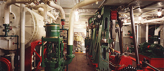
Engineering, Building, and Architecture

Not many museums collect houses. The National Museum of American History has four, as well as two outbuildings, 11 rooms, an elevator, many building components, and some architectural elements from the White House. Drafting manuals are supplemented by many prints of buildings and other architectural subjects. The breadth of the museum's collections adds some surprising objects to these holdings, such as fans, purses, handkerchiefs, T-shirts, and other objects bearing images of buildings.

The engineering artifacts document the history of civil and mechanical engineering in the United States. So far, the Museum has declined to collect dams, skyscrapers, and bridges, but these and other important engineering achievements are preserved through blueprints, drawings, models, photographs, sketches, paintings, technical reports, and field notes.

This Peerless brand toy steam engines was manufactured around 1900. The overtype engine consists of a horizontal boiler with sight glass and lever safety valve. A slide valve engine powers a flywheel on top of the boiler.
Description (Brief)
This Peerless brand toy steam engines was manufactured around 1900. The overtype engine consists of a horizontal boiler with sight glass and lever safety valve. A slide valve engine powers a flywheel on top of the boiler. The engine sits on an iron frame which is painted with red stripes.
Location
Currently not on view
date made
ca 1900
ID Number
MC.329002
catalog number
329002
accession number
278175
This Weeden No. 238 toy steam engine was manufactured by the Weeden Manufacturing Company of New Bedford, Massachusetts from 1918 until 1940. The vertical engine has a firebox below a steel boiler with chimney.
Description (Brief)
This Weeden No. 238 toy steam engine was manufactured by the Weeden Manufacturing Company of New Bedford, Massachusetts from 1918 until 1940. The vertical engine has a firebox below a steel boiler with chimney. A vertical slide valve engine is attached to a flywheel on the upper half of the boiler.
The Weeden Manufacturing Company was founded in New Bedford, Massachusetts by William M. Weeden in the early 1880s, originally producing a variety of tinplate household items. In 1884 it introduced the Weeden No. 1 Steam engine as “a new and great premium for boys” who were subscribers to the Youth’s Companion magazine. Weeden made over a hundred different models of toy steam engines until the company ceased operations in 1952.
Location
Currently not on view
date made
early 20th century
ID Number
MC.328948
catalog number
328948
accession number
278175
Crosby Steam Gauge & Valve Co. of Boston, Massachusetts, manufactured this steam engine indicator, serial number 1074D.
Description
Crosby Steam Gauge & Valve Co. of Boston, Massachusetts, manufactured this steam engine indicator, serial number 1074D. It consists of a steel piston; a vented brass cylinder; an external, double wound spring, which can be changed; a large drum with a spiral spring and a single record; and a brass stylus. Accompanying the indicator is a box with twelve springs and some small tools.
An engine indicator is an instrument for graphically recording the pressure versus piston displacement through an engine stroke cycle. Engineers use the resulting diagram to check the design and performance of the engine.
A mechanical indicator consists of a piston, spring, stylus, and recording system. The gas pressure of the cylinder deflects the piston and pushes against the spring, creating a linear relationship between the gas pressure and the deflection of the piston against the spring. The deflection is recorded by the stylus on a rotating drum that is connected to the piston. Most indicators incorporate a mechanical linkage to amplify the movement of the piston to increase the scale of the record.
When the ratio of the frequency of the pressure variation to the natural frequency of the system is small, then the dynamic deflection is equal to the static deflection. To design a system with a high natural frequency, the mass of the piston, spring, stylus, and mechanical linkage must be small, but the stiffness of the spring must be high. The indicator is subjected to high temperatures and pressures and rapid oscillations, imposing a limitation on the reduction in mass. Too stiff a spring will result in a small displacement of the indicator piston and a record too small to measure with accuracy. Multiplication of the displacement will introduce mechanical ad dynamic errors.
The parameters of the problem for designing an accurate and trouble free recorder are such that there is no easy or simple solution. Studying the variety of indicators in the collection shows how different inventors made different compromises in their designs.
Location
Currently not on view
maker
Crosby Steam Gage & Valve Company
ID Number
MC.316797
catalog number
316797
accession number
228496
patent number
1074D
This toy steam engine was manufactured by the Bassett-Lowke Company of Northampton, England during the early 20th century.
Description (Brief)
This toy steam engine was manufactured by the Bassett-Lowke Company of Northampton, England during the early 20th century. The vertical slide valve engine consists of a firebox, vertical boiler, and chimney on a cast iron base.
Live steam toys enjoyed a period of popularity from the 1880s until the 1930s. The miniature steam engines were marketed as both toys and instructive devices that mimicked full-scale steam-powered machines and allowed every boy and girl to be their own engineer. In toy steam engines, a heating source is introduced into the firebox below the boiler (early toys used lit wicks fueled by denatured alcohol, later toys used electricity) which heated the water to produce the steam pressure that ran the engine. A variety of accessories could be powered by the engine; attachments included windmills, pumps, grinders, and electric lights.
Location
Currently not on view
date made
ca 1900
ID Number
MC.328940
catalog number
328940
accession number
278175
date made
1855
patent date
1855-07-31
inventor
Ericsson, John
ID Number
MC.251279
catalog number
251279
accession number
48865
patent number
13,348
This oiler was submitted to the U.S. Patent Office with the application for the patent issued to Peter D. Hay (assignor to the Michigan Lubricator Co.), of Detroit, Michigan, June 9, 1888, no.
Description
This oiler was submitted to the U.S. Patent Office with the application for the patent issued to Peter D. Hay (assignor to the Michigan Lubricator Co.), of Detroit, Michigan, June 9, 1888, no. 384762.
The model represents a sight-feed oiler in which the oil is contained in a cylindrical glass reservoir and flows by gravity through a needle valve to the bearing into which the oiler is screwed. The needle of the needle valve when closed is held against its seat by a light spring. It is opened by lifting the needle and giving it a short turn so that a pin on the shaft rises out of a slot and rests on the top edge of a brass thumb nut screwed into the central pot of the oiler. This nut may be run up or down on its threads and so determine the amount by which the needle will be raised and held from its seat and so control the rate at which oil is fed from the reservoir. The nut carries a spring-held pin that rests in shallow recesses in the top of the oiler and holds the nut in the position in which it is set and will not permit the nut to be jarred around by the vibration of the machine to which it is attached.
Reference:
This description comes from the 1939 Catalog of the Mechanical Collections of the Division of Engineering United States Museum Bulletin 173 by Frank A. Taylor.
Location
Currently not on view
date made
1888
patent date
1888-06-19
inventor
Hay, Peter D.
ID Number
MC.309248
catalog number
309248
accession number
89797
patent number
384,762
Novelty Iron Works manufactured this McNaught steam engine indicator. It consists of a brass piston and cylinder with a steel spring under the pencil holder.
Description
Novelty Iron Works manufactured this McNaught steam engine indicator. It consists of a brass piston and cylinder with a steel spring under the pencil holder. It takes a direct reading with no linkage on a large drum.
An engine indicator is an instrument for graphically recording the pressure versus piston displacement through an engine stroke cycle. Engineers use the resulting diagram to check the design and performance of the engine.
A mechanical indicator consists of a piston, spring, stylus, and recording system. The gas pressure of the cylinder deflects the piston and pushes against the spring, creating a linear relationship between the gas pressure and the deflection of the piston against the spring. The deflection is recorded by the stylus on a rotating drum that is connected to the piston. Most indicators incorporate a mechanical linkage to amplify the movement of the piston to increase the scale of the record.
When the ratio of the frequency of the pressure variation to the natural frequency of the system is small, then the dynamic deflection is equal to the static deflection. To design a system with a high natural frequency, the mass of the piston, spring, stylus, and mechanical linkage must be small, but the stiffness of the spring must be high. The indicator is subjected to high temperatures and pressures and rapid oscillations, imposing a limitation on the reduction in mass. Too stiff a spring will result in a small displacement of the indicator piston and a record too small to measure with accuracy. Multiplication of the displacement will introduce mechanical ad dynamic errors.
The parameters of the problem for designing an accurate and trouble free recorder are such that there is no easy or simple solution. Studying the variety of indicators in the collection shows how different inventors made different compromises in their designs.
Location
Currently not on view
ID Number
MC.319481
catalog number
319481
accession number
237917
The Fulton Company of Knoxville, Tennessee manufactured this Sylphon Regitherm thermostat around 1910. The thermostat could be set between 60 and 80 degrees.
Description
The Fulton Company of Knoxville, Tennessee manufactured this Sylphon Regitherm thermostat around 1910. The thermostat could be set between 60 and 80 degrees. The Regitherm operated by the expansion and contraction of the metal bellows seen at the far left of the object, changing the temperature on the thermostat varied the liquid level inside the bellows. Once the bellows contracted to a certain level, the liquid exerted a pressure on the mechanism that opened the damper system on the furnace, increasing the heat.
The ubiquity of thermostats in 21st century homes shrouds the decades of innovation, industrial design, and engineering that went into making them an everyday object in almost every home. In the early 20th century, a majority of American households still heated their homes with manually operated furnaces that required a trip down to the basement and stoking the coal fired furnace. Albert Butz’s “damper-flapper” system was patented in 1886 and allowed user to set the thermostat to a certain temperature which would open a damper to the furnace, increasing the fire and heating the house. Progressive innovations allowed for the thermostats to use gas lines, incorporate electricity, turn on at a set time, include heating and cooling in one mechanism, and even connect to the internet.
Location
Currently not on view
ID Number
2008.0011.18
accession number
2008.0011
catalog number
2008.0011.18
The Weeden Manufacturing Company of New Bedford, Massachusetts, manufactured the Weeden No. 900 toy steam engine from 1935 until 1940. The Weeden No. 900 was an electrically heated steam engine, and the two prongs that would be plugged into a cord can be seen under the boiler.
Description (Brief)
The Weeden Manufacturing Company of New Bedford, Massachusetts, manufactured the Weeden No. 900 toy steam engine from 1935 until 1940. The Weeden No. 900 was an electrically heated steam engine, and the two prongs that would be plugged into a cord can be seen under the boiler. The plate above the prongs details the volts, watts, and catalog number of the engine. The engine consists of a horizontal boiler powering a horizontal slide valve engine with flyball governor that powers a flywheel.
The Weeden Manufacturing Company was founded in New Bedford, Massachusetts by William M. Weeden in the early 1880s, originally producing a variety of tinplate household items. In 1884 it introduced the Weeden No. 1 Steam engine as “a new and great premium for boys” who were subscribers to the Youth’s Companion magazine. Weeden made over a hundred different models of toy steam engines until the company ceased operations in 1952.
Location
Currently not on view
ID Number
MC.328953
catalog number
328953
accession number
278175
This toy steam engine was made by an unknown German company during the early 20th century. The toy consists of a horizontal boiler with chimney on a simulated brickwork firebox. The horizontal slide valve engine powers a flywheel with a centrifugal flyball governor.
Description (Brief)
This toy steam engine was made by an unknown German company during the early 20th century. The toy consists of a horizontal boiler with chimney on a simulated brickwork firebox. The horizontal slide valve engine powers a flywheel with a centrifugal flyball governor. The boiler and engine are mounted on a cast iron plate.
Live steam toys enjoyed a period of popularity from the 1880s until the 1930s. The miniature steam engines were marketed as both toys and instructive devices that mimicked full-scale steam-powered machines and allowed every boy and girl to be their own engineer. In toy steam engines, a heating source is introduced into the firebox below the boiler (early toys used lit wicks fueled by denatured alcohol, later toys used electricity) which heated the water to produce the steam pressure that ran the engine. A variety of accessories could be powered by the engine; attachments included windmills, pumps, grinders, and electric lights.
Location
Currently not on view
date made
early 20th century
ID Number
MC.322908
catalog number
322908
accession number
220719
Slip Joint Pliers are for gripping round work, such as pipes and nuts. These pliers are made of steel, have an adjustable grip and yellow plastic covered handles. Made by Fuller Tools. Fuller first started in Whitestone New York in the 1930's.
Description
Slip Joint Pliers are for gripping round work, such as pipes and nuts. These pliers are made of steel, have an adjustable grip and yellow plastic covered handles. Made by Fuller Tools. Fuller first started in Whitestone New York in the 1930's. In 1944 two Canadian brothers, Stanley and Lloyd Davis set up production and made tools near Montreal. In the early 1990's, Fuller moved to Montreal and the US manufacturing facility was consolidated with the Canadian facility. These pliers were used by Jillian Gross while working for Habitat for Humanity, a not-for-profit, non-government organization advocating affordable housing around the world.
When Hurricane Katrina struck the Gulf Coast in August 2005, Jillian Gross had worked with Habitat for Humanity for three years learning woodworking and house-building skills. Groups such as Habitat for Humanity marshaled volunteers, tools and lumber to step in when it became clear that normal avenues of housing assistance were overwhelmed.
In November 2005, Habitat for Humanity launched “America Builds on the National Mall,” a demonstration house-building marathon in Washington, D.C. in which the basic components of 51 homes were assembled within a week and shipped to the Gulf Coast. Upon completion of the project Ms. Gross, one of the house building leaders during this event, donated her tool belt, tools and protective wear to the Smithsonian Institution. The plyers were found in the tool belt.
Location
Currently not on view
ID Number
2005.0276.23
catalog number
2005.0276.23
accession number
2005.0276
This model was submitted to the U.S. Patent Office with application for the patent issued to S. Lloyd Wiegand, of Philadelphia, Pennsylvania, August 6, 1867, no.
Description
This model was submitted to the U.S. Patent Office with application for the patent issued to S. Lloyd Wiegand, of Philadelphia, Pennsylvania, August 6, 1867, no. 67621.
This model is of a boiler having water tubes made up of large tubes closed at the ends with smaller tubes suspended within the large tubes to provide a circulation of steam and water upward in the smaller tubes and of the cooler water down ward in the annular spaces between the larger and smaller tubes. The inventor suggests the use of tubes of different metals to produce a galvanic action for the purpose of preventing deposits of scale within the tubes.
The boiler represented by the model consists of a series of vertical tubes suspended into the furnace from a horizontal header across the top of the boiler setting. The tubes closed at their lower ends, and within each tube is one of smaller diameter. The smaller tubes are suspended from a plate within the header. The headers connecting each row of tubes across the boiler are, in turn, connected by a longitudinal drum above them.
Reference:
This description comes from the 1939 Catalog of the Mechanical Collections of the Division of Engineering United States Museum Bulletin 173 by Frank A. Taylor.
Location
Currently not on view
date made
1867
patent date
1867-08-06
inventor
Wiegand, S. Lloyd
ID Number
MC.309209
catalog number
309209
accession number
89797
patent number
67,621
This toy electric engine was made by an unknown maker around 1900. The reciprocating engine has a 3.5-inch flywheel on a cast-iron base.Currently not on view
Description (Brief)
This toy electric engine was made by an unknown maker around 1900. The reciprocating engine has a 3.5-inch flywheel on a cast-iron base.
Location
Currently not on view
date made
ca 1900
ID Number
MC.329035
catalog number
329035
accession number
278175
This toy steam engine was manufactured by the Weeden Manufacturing Company of New Bedford, Massachusetts during the early 20th century. This vertical engine has a tin firebox, brass boiler, and vertical slide valve engine.
Description (Brief)
This toy steam engine was manufactured by the Weeden Manufacturing Company of New Bedford, Massachusetts during the early 20th century. This vertical engine has a tin firebox, brass boiler, and vertical slide valve engine. The upper stack is homemade and was added to the original Weeden model at a later date.
The Weeden Manufacturing Company was founded in New Bedford, Massachusetts by William M. Weeden in the early 1880s, originally producing a variety of tinplate household items. In 1884 it introduced the Weeden No. 1 Steam engine as “a new and great premium for boys” who were subscribers to the Youth’s Companion magazine. Weeden made over a hundred different models of toy steam engines until the company ceased operations in 1952.
Location
Currently not on view
date made
late 19th century
ID Number
MC.328946
catalog number
328946
accession number
278175
This toy steam engine was built by the Ernst Plank Company of Nuremburg, Germany, during the late 19th or early 20th century.
Description (Brief)
This toy steam engine was built by the Ernst Plank Company of Nuremburg, Germany, during the late 19th or early 20th century. The toy consists of a black firebox below a horizontal boiler that powers a horizontal slide valve engine that is connected to two flywheels.
Live steam toys enjoyed a period of popularity from the 1880s until the 1930s. The miniature steam engines were marketed as both toys and instructive devices that mimicked full-scale steam-powered machines and allowed every boy and girl to be their own engineer. In toy steam engines, a heating source is introduced into the firebox below the boiler (early toys used lit wicks fueled by denatured alcohol, later toys used electricity) which heated the water to produce the steam pressure that ran the engine. A variety of accessories could be powered by the engine; attachments included windmills, pumps, grinders, and electric lights.
Location
Currently not on view
date made
ca 1900
ID Number
MC.329005
catalog number
329005
accession number
278175
This manographe, or indicator, was purchased by Professor W. H. Kenerson around 1907.
Description
This manographe, or indicator, was purchased by Professor W. H. Kenerson around 1907. He used it in making tests of the Brayton Oil Engine, National Museum of American History catalog number 313.703, at Brown University.
A pivoted mirror reflects a beam of light to a photosensitive plate or paper. Changes in pressure in the engine cylinder cause the mirror to oscillate up and down; a pin and eccentric actuated by a flexible shaft connected to the engine shaft cause the mirror to oscillate from side to side.
The indicator is housed in a wooden box that is 5 inches by 6 inches by 14 inches, with a brass pipe fitting and gear box at one end. The opposite end is open to receive a plate holder of a ground glass. A T-shaped tube lets light into one side, and an adjustable prism inside directs the light to the mirror. The flexible shaft is 32 inches long and covered with black fabric. Four plate holders, one ground glass, a steel petcock and a tapered hollow steel plug are included with the instrument. It is marked “Manographe Hospitalier-Carpentier, Brevete, S G D G, J. Carpentier, Paris.”
An engine indicator is an instrument for graphically recording the pressure versus piston displacement through an engine stroke cycle. Engineers use the resulting diagram to check the design and performance of the engine.
A mechanical indicator consists of a piston, spring, stylus, and recording system. The gas pressure of the cylinder deflects the piston and pushes against the spring, creating a linear relationship between the gas pressure and the deflection of the piston against the spring. The deflection is recorded by the stylus on a rotating drum that is connected to the piston. Most indicators incorporate a mechanical linkage to amplify the movement of the piston to increase the scale of the record.
When the ratio of the frequency of the pressure variation to the natural frequency of the system is small, then the dynamic deflection is equal to the static deflection. To design a system with a high natural frequency, the mass of the piston, spring, stylus, and mechanical linkage must be small, but the stiffness of the spring must be high. The indicator is subjected to high temperatures and pressures and rapid oscillations, imposing a limitation on the reduction in mass. Too stiff a spring will result in a small displacement of the indicator piston and a record too small to measure with accuracy. Multiplication of the displacement will introduce mechanical ad dynamic errors.
The parameters of the problem for designing an accurate and trouble free recorder are such that there is no easy or simple solution. Studying the variety of indicators in the collection shows how different inventors made different compromises in their designs.
Location
Currently not on view
ID Number
MC.313704
catalog number
313704
accession number
192776
This toy punch press was manufactured by an unknown maker during the early 20th century. The toy punch press was made of cast metal and could be powered by connecting its pulley directly to an engine or a line shaft.Currently not on view
Description (Brief)
This toy punch press was manufactured by an unknown maker during the early 20th century. The toy punch press was made of cast metal and could be powered by connecting its pulley directly to an engine or a line shaft.
Location
Currently not on view
date made
ca 1900
ID Number
MC.329086
catalog number
329086
accession number
278175
This model was submitted to the U.S. Patent Office with the application for Patent no. 111088, issued to Alexander K. Rider, of New York, New York, January 17, 1871, reissued August 24, 188-, no.
Description
This model was submitted to the U.S. Patent Office with the application for Patent no. 111088, issued to Alexander K. Rider, of New York, New York, January 17, 1871, reissued August 24, 188-, no. 9353.
This engine consists of a power piston and a transfer piston so connected with valves and passages that the cold air is received and compressed in the same cylinder in which the hot air performs its work. Its simple construction is an improvement on the John Ericsson hot-air engines of 1855-1858.
A vertical cylinder contains two independent pistons with suitable valves that permit cold air to be drawn into the cylinder, compressed, circulated between heated furnace walls, expanded under a power piston and then exhausted. The upper piston is equipped with two spring-closed intake valves that open on the upstroke of the piston allowing air to fill the cylinder between the upper and lower pistons. This air is then compressed on the downstroke of the upper piston until the pressure is sufficient to open a valve in a passage leading to a heated space surrounding the furnace. The heated and compressed air then passes into the cylinder below the lower piston where it expands, performing work against the piston.
Reference:
This description comes from the 1939 Catalog of the Mechanical Collections of the Division of Engineering United States Museum Bulletin 173 by Frank A. Taylor.
Location
Currently not on view
date made
1871
patent date
1871-01-17
inventor
Rider, Alexander K.
ID Number
ER.308714
accession number
89797
catalog number
308714
patent number
111,088
Crosby Steam Gauge & Valve Co. of Boston, Massachusetts, manufactured this steam engine indicator, serial number 3309. It consists of a piston, which is stuck inside the cylinder. A brass stylus can record onto a large small drum with a spiral spring and a single record.
Description
Crosby Steam Gauge & Valve Co. of Boston, Massachusetts, manufactured this steam engine indicator, serial number 3309. It consists of a piston, which is stuck inside the cylinder. A brass stylus can record onto a large small drum with a spiral spring and a single record. Accompanying the indicator is a box with twelve springs and a spring wrench.
An engine indicator is an instrument for graphically recording the pressure versus piston displacement through an engine stroke cycle. Engineers use the resulting diagram to check the design and performance of the engine.
A mechanical indicator consists of a piston, spring, stylus, and recording system. The gas pressure of the cylinder deflects the piston and pushes against the spring, creating a linear relationship between the gas pressure and the deflection of the piston against the spring. The deflection is recorded by the stylus on a rotating drum that is connected to the piston. Most indicators incorporate a mechanical linkage to amplify the movement of the piston to increase the scale of the record.
When the ratio of the frequency of the pressure variation to the natural frequency of the system is small, then the dynamic deflection is equal to the static deflection. To design a system with a high natural frequency, the mass of the piston, spring, stylus, and mechanical linkage must be small, but the stiffness of the spring must be high. The indicator is subjected to high temperatures and pressures and rapid oscillations, imposing a limitation on the reduction in mass. Too stiff a spring will result in a small displacement of the indicator piston and a record too small to measure with accuracy. Multiplication of the displacement will introduce mechanical ad dynamic errors.
The parameters of the problem for designing an accurate and trouble free recorder are such that there is no easy or simple solution. Studying the variety of indicators in the collection shows how different inventors made different compromises in their designs.
Location
Currently not on view
maker
Crosby Steam Gage & Valve Company
ID Number
MC.316795
catalog number
316795
accession number
228496
Henry Essex of Buffalo, New York received patent number 723,660 in 1903 for this design of a caloric engine. The engine is a “hot air” or caloric engine, where heated air powers the piston before being cooled and returning to be heated, continuously producing work.
Description (Brief)
Henry Essex of Buffalo, New York received patent number 723,660 in 1903 for this design of a caloric engine. The engine is a “hot air” or caloric engine, where heated air powers the piston before being cooled and returning to be heated, continuously producing work. The engine consists of a flywheel at one end with displacing rod, a heating element in the center with two piston inside, and cool air pockets on either side of the center.
Location
Currently not on view
date made
1903
ID Number
MC.329058
catalog number
329058
accession number
278175
Ernst Plank produced this toy steam engine during the early 20th century. The toy has a tan fire box below a horizontal boiler with steam whistle, safety valve, and throttle.
Description (Brief)
Ernst Plank produced this toy steam engine during the early 20th century. The toy has a tan fire box below a horizontal boiler with steam whistle, safety valve, and throttle. The steam line powers a small oscillating engine mounted on a two pole generator that provides electricity to twin Marx-manufactured lamps on metal scaffolding.
Ernst Plank founded his company in Nuremburg, Germany in 1866. The company was well known for manufacturing a variety of metal toys like steam locomotives, stationary steam engines, early photography equipment, and magic lanterns until its dissolution in 1935.
Location
Currently not on view
ID Number
MC.329059
catalog number
329059
accession number
278175
General Electric manufactured this Thermal Control thermostat around 1933. The thermostat came equipped with a Telechron synchronous motor that powered the clock attached to the thermostat.
Description
General Electric manufactured this Thermal Control thermostat around 1933. The thermostat came equipped with a Telechron synchronous motor that powered the clock attached to the thermostat. The clock allowed the furnace to turn on and off at a certain time, and the thermostat has two wheels on the right and the left, which allowed the home owner to set a desired temperature during the day and during the evening.
The ubiquity of thermostats in 21st century homes shrouds the decades of innovation, industrial design, and engineering that went into making them an everyday object in almost every home. In the early 20th century, a majority of American households still heated their homes with manually operated furnaces that required a trip down to the basement and stoking the coal fired furnace. Albert Butz’s “damper-flapper” system was patented in 1886 and allowed home owner to set the thermostat to a certain temperature which would open a damper to the furnace, increasing the fire and heating the house. Progressive innovations allowed for the thermostats to use gas lines, incorporate electricity, turn on at a set time, include heating and cooling in one mechanism, and even connect to the internet.
Location
Currently not on view
ID Number
2008.0011.06
accession number
2008.0011
catalog number
2008.0011.06
This model was submitted to the U.S. Patent Office with the application for the patent issued to George H. Corliss, of Providence, Rhode Island, May 27, 1879, no.
Description
This model was submitted to the U.S. Patent Office with the application for the patent issued to George H. Corliss, of Providence, Rhode Island, May 27, 1879, no. 215798.
The model represents a bank of curved water tubes joined in vertical rows by the separate cases or tube ends, which are the subject of the patent. Each end of each tube is threaded into the side of the cylindrical casting, which is provided with machined surfaces that allow the separate castings to go together tightly to form a continuous tube sheet or header for each vertical row of tubes. The castings forming each header are held together by a single long bolt, which threads into a casting that forms a common connector along the lower ends of the vertical headers.
Reference:
This description comes from the 1939 Catalog of the Mechanical Collections of the Division of Engineering United States Museum Bulletin 173 by Frank A. Taylor.
Location
Currently not on view
date made
1879
patent date
1879-05-27
inventor
Corliss, George H.
ID Number
MC.309214
catalog number
309214
accession number
89797
patent number
215,798
This toy steam engine was made by the Märklin Company during the early 20th century. This toy steam engine consists of a firebox, horizontal brass boiler, chimney stack, and horizontal engine with flyball governor that powers a flywheel.
Description (Brief)
This toy steam engine was made by the Märklin Company during the early 20th century. This toy steam engine consists of a firebox, horizontal brass boiler, chimney stack, and horizontal engine with flyball governor that powers a flywheel. The boiler and engine are mounted on a tin base.
The Märklin Company was established in 1859 in the town of Göppingen, Germany by tin smith Theodor Friedrich Wilhelm Märklin. Märklin began his business with the production of tin doll houses, but the company soon began producing a variety of tinplate and metal items, eventually specializing in toys that included steam engines such as this one.
Location
Currently not on view
date made
mid 20th century
ID Number
MC.329031
catalog number
329031
accession number
278175

Our collection database is a work in progress. We may update this record based on further research and review. Learn more about our approach to sharing our collection online.

If you would like to know how you can use content on this page, see the Smithsonian's Terms of Use. If you need to request an image for publication or other use, please visit Rights and Reproductions.