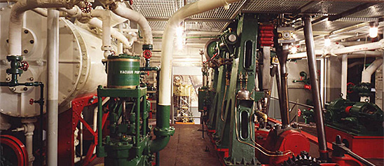
Engineering, Building, and Architecture

Not many museums collect houses. The National Museum of American History has four, as well as two outbuildings, 11 rooms, an elevator, many building components, and some architectural elements from the White House. Drafting manuals are supplemented by many prints of buildings and other architectural subjects. The breadth of the museum's collections adds some surprising objects to these holdings, such as fans, purses, handkerchiefs, T-shirts, and other objects bearing images of buildings.

The engineering artifacts document the history of civil and mechanical engineering in the United States. So far, the Museum has declined to collect dams, skyscrapers, and bridges, but these and other important engineering achievements are preserved through blueprints, drawings, models, photographs, sketches, paintings, technical reports, and field notes.

This model was submitted to the U.S. Patent Office with the application for the patent issued to Francis B. Stevens, November 3, 1863, no.
Description
This model was submitted to the U.S. Patent Office with the application for the patent issued to Francis B. Stevens, November 3, 1863, no. 40510.
The condenser represented in the model consists of a large vertical cylinder and pump plunger with various connected chambers designed to function as a condenser, a condenser air pump, and feed-water hot well and heater.
The invention “consists in simplifying the apparatus that condenses the steam discharged by the first eduction from the cylinder of a condensing steam engine by closing the hot well of the engine against the atmosphere and by keeping a portion of the space of the hot well free from water, and by delivering the steam discharged from the cylinder by the first eduction into the hot well, so that it may be condensed or partially condensed by the water delivered by the air-pump into the hot well.” The hot well is thus made “to act also as an additional condenser and dispense altogether with an additional air pump to draw the water from the additional condenser.”
Reference:
This description comes from the 1939 Catalog of the Mechanical Collections of the Division of Engineering United States Museum Bulletin 173 by Frank A. Taylor.
Location
Currently not on view
date made
1863
patent date
1863-11-03
inventor
Stevens, Francis B.
ID Number
MC.309238
catalog number
309238
accession number
89797
patent number
40,510
This is a rectangular bucket divided by a central splitter edge into two hollow semicylindrical compartments. The bucket is designed to receive and divide the jet upon the slitter edge and direct the water to either side, discharging at the sides.
Description
This is a rectangular bucket divided by a central splitter edge into two hollow semicylindrical compartments. The bucket is designed to receive and divide the jet upon the slitter edge and direct the water to either side, discharging at the sides. No provision is made for the flow of water in a radial direction along bucket, and the outer end of the bucket makes sharp angles with the sides and bottom. The extreme lip of the bucket is very slightly depressed, suggesting the notched lip developed later. The back of the bucket is provided with lugs, which slip over the rim of the wheel center to which it is attached by the bolts passing through the lugs and rim parallel to the shaft. The bucket is made of cast iron, measures about 11.5 inches wide, and weighs 30 pounds. This bucket was made about 1901.
Reference:
This description comes from the 1939 Catalog of the Mechanical Collections of the Division of Engineering United States Museum Bulletin 173 by Frank A. Taylor.
Location
Currently not on view
date made
ca 1901
ID Number
MC.310386
catalog number
310386
accession number
117363
This model was submitted to the U.S. Patent Office with the application for the patent issued to Henry R. Worthington, of New York, New York, June 20, 1871, no.
Description
This model was submitted to the U.S. Patent Office with the application for the patent issued to Henry R. Worthington, of New York, New York, June 20, 1871, no. 116131.
The model is a relief panel showing a section through the two steam cylinders of a duplex pump arranged to use steam at boiler pressure in one steam cylinder of small diameter, expand the exhaust steam in a receiver of much larger volume than the small cylinder, and use the steam at low pressure in a second cylinder of larger diameter. This arrangement was devised to permit the use of steam expansively in a duplex pump without the use of two compound cylinders, as was formerly the method.
Reference:
This description comes from the 1939 Catalog of the Mechanical Collections of the Division of Engineering United States Museum Bulletin 173 by Frank A. Taylor.
Location
Currently not on view
date made
1871
patent date
1871-06-20
inventor
Worthington, Henry R.
ID Number
ER.308681
accession number
89797
catalog number
308681
patent number
116,131
This model was submitted to the U.S. Patent Office with the application for the patent issued to J. and F. M. Cottle, October 21, 1879, no.
Description
This model was submitted to the U.S. Patent Office with the application for the patent issued to J. and F. M. Cottle, October 21, 1879, no. 220751.
This mill has a double-rimmed steel wind wheel made up of small wedge-shaped vanes, which are removable to permit regulation of the power of the mill. The wind wheel cannot be swung out of its position, but the shaft is carried in sliding bearings so that the gear on the shaft can be disengaged to let the wheel run free. It is equipped with a selective gear transmission. The model shows the mill attached to the bucket chain of a well.
Reference:
This description comes from the 1939 Catalog of the Mechanical Collections of the Division of Engineering United States Museum Bulletin 173 by Frank A. Taylor.
Location
Currently not on view
date made
1879
patent date
1879-10-21
inventor
Cottle, Zorah
Cottle, F. M.
ID Number
ER.309131
accession number
89797
catalog number
309131
patent number
220,751
This model was submitted to the U.S. Patent Office with the application for the patent issued to George H. Corliss, August 8, 1882, no.
Description
This model was submitted to the U.S. Patent Office with the application for the patent issued to George H. Corliss, August 8, 1882, no. 262209.
The model represents a flyball governor in which the motion of the slide, owing to a change in the speed of the engine to which the governor is attached, not only changes the position of the cut-off or throttle devices to regulate the speed of the engine but also changes the gear ratio between the engine and the governor to change the speed of the governor relative to the speed of the engine.
When the governor speed is increased by an increase in the speed of the engine, the balls rise and communicate motion to a slide, which, in turn, affects the throttle or cut-off to return the engine to its lower speed. At the same time the motion of the slide shifts a friction roller on its driving disk so that the governor speed is increased relative to the engine causing an additional motion of the slide in the same direction. As a result, the governor slide is given a greater motion for a given change in speed than would otherwise result.
Reference:
This description comes from the 1939 Catalog of the Mechanical Collections of the Division of Engineering United States Museum Bulletin 173 by Frank A. Taylor.
Location
Currently not on view
date made
1882
patent date
1882-08-08
inventor
Corliss, George H.
ID Number
MC.308715
catalog number
308715
accession number
89797
patent number
262,209
This model was submitted to the U.S. Patent Office with the application for the patent issued to Joseph Wotapek, of New York, New York, May 6, 1884, no.
Description
This model was submitted to the U.S. Patent Office with the application for the patent issued to Joseph Wotapek, of New York, New York, May 6, 1884, no. 298329; assigned to the Nation Manufacturing Co.
The improvement involved in this injector is the use of a nozzle holder by which the scale-incrusted nozzle or tube of the injector may be easily removed to permit cleaning. The holder is threaded into the shell of the injector from which it and the tube are drawn by unscrewing the bolder. The holder turns independently of the tube so that the tube itself is not subjected to torsion when being withdrawn from the shell.
Reference:
This description comes from the 1939 Catalog of the Mechanical Collections of the Division of Engineering United States Museum Bulletin 173 by Frank A. Taylor.
Location
Currently not on view
date made
1884
patent date
1884-05-06
inventor
Wotapek, Joseph
ID Number
MC.309181
catalog number
309181
patent number
298,329
accession number
89797
This model was submitted to the U.S. Patent Office with the application for the patent issued to John Warren, of Detroit, Michigan, April 20, 1880, no.
Description
This model was submitted to the U.S. Patent Office with the application for the patent issued to John Warren, of Detroit, Michigan, April 20, 1880, no. 226813.
The motor represented is of the class intended to operate light machinery such as a phonograph but differs from most of the class in that it employs a spiral spring instead of the usual coil spring. It converts the rectilinear motion of the spring into rotary motion and equalizes the varying tension of the spring.
The free end of the spring carries a nut that engages in a spiral-grooved motor shaft, which revolves at the axis of the spring. A hand crank, worm, and worm wheel are used to compress the spring by turning the shaft in the reverse direction. The power is taken from a bevel gear on the shaft. A ball nut, which employs a ball to follow in the groove of the shaft, is used because an ordinary nut would not work in the groove of varying pitch. The varying pitch is used to compensate for the varying tension of the spring.
Reference:
This description comes from the 1939 Catalog of the Mechanical Collections of the Division of Engineering United States Museum Bulletin 173 by Frank A. Taylor.
Location
Currently not on view
date made
1880
patent date
1880-04-20
inventor
Warren, John
ID Number
MC.308835
catalog number
308835
accession number
89797
patent number
226,813
This model was submitted to the U.S. Patent Office with its application for Patent no. 217758, issued to James M. Whiting, of Providence, Rhode Island, July 22, 1879.This is an example of combined air and steam engines, many designs of which have been proposed and built.
Description
This model was submitted to the U.S. Patent Office with its application for Patent no. 217758, issued to James M. Whiting, of Providence, Rhode Island, July 22, 1879.
This is an example of combined air and steam engines, many designs of which have been proposed and built. In this engine the use of steam is intended to reduce the bulk of the heated air required to operate an engine of a given capacity and consequently reduce the size of the engine.
The model shows a vertical fire-tube steam boiler of ordinary construction above the tubes of which is placed a hollow drum that is heated by the hot gases from the boiler. There is also a small steam pump and a vertical high-speed steam engine of the slide-valve type. Steam from the boiler is mixed with the heated air in the upper drum, and the mixture of heated air and steam is led directly to the engine and expanded. The air pump supplies air to the heated drum.
Reference:
This description comes from the 1939 Catalog of the Mechanical Collections of the Division of Engineering United States Museum Bulletin 173 by Frank A. Taylor.
Location
Currently not on view
date made
1879
patent date
1879-07-22
inventor
Whiting, James M.
ID Number
ER.251285
accession number
48865
catalog number
251285
patent number
217,758
This model was submitted to the U.S. Patent Office with the application for the patent issued to Adam S. Cameron, of New York, New York, November 10, 1874, no.
Description
This model was submitted to the U.S. Patent Office with the application for the patent issued to Adam S. Cameron, of New York, New York, November 10, 1874, no. 156769.
This invention relates to a design of pump valves so controlled by spindles and guides that the necessity of central bearings in the valve seat is avoided, leaving a clear circular opening for the passage of the fluid being pumped.
The model represents a valve chest of a pump cylinder equipped with four valves arranged in pairs, in which one valve is located above the other. In each pair the valve stem of the upper valve projects upward into a hollow plug in the top of the valve chest and downward into a socket in the lower valve. The socket of the lower valve extends downward into a hollow plug or guide in the bottom of the valve chest. Both valves are spring closed and the lower valve is free to move independently of the upper valve.
Reference:
This description comes from the 1939 Catalog of the Mechanical Collections of the Division of Engineering United States Museum Bulletin 173 by Frank A. Taylor.
Location
Currently not on view
date made
1874
patent date
1874-11-10
inventor
Cameron, Adam S.
ID Number
ER.308686
accession number
89797
catalog number
308686
patent number
156,769
associated institution
Faesch & Piccard
ID Number
EM.315850
catalog number
315850
accession number
221414
This model was filed with the application to the U.S. Patent Office for the patent issued to Lucius J. Knowles, of Worcester, Massachusetts, April 1, 1879, no.
Description
This model was filed with the application to the U.S. Patent Office for the patent issued to Lucius J. Knowles, of Worcester, Massachusetts, April 1, 1879, no. 231823.
The model represents the steam cylinders of a duplex pump fitted with what the inventor calls auxiliary engines to operate the valves of each cylinder when it is desired to use one cylinder of a duplex pump without the other. Actually the piston of the auxiliary engine is the valve of the main cylinder and the invention is in effect a one cylinder “simplex” pump with steam-actuated valve. This is one of the earliest uses of the steam-actuated valve for steam pumps.
The auxiliary cylinder forms the steam chest and valve ports of the main cylinder while the auxiliary piston acts as the valve. The auxiliary piston has its own valve system, which consists of ports in the auxiliary cylinder wall connected to the main steam passages and so located that they will register with openings in the auxiliary piston when the auxiliary piston is given a slight twist at the end of the main piston’s stroke. These openings connect to passages in the auxiliary cylinder to cause the auxiliary piston to move to the other end of the cylinder and so reverse the stroke of the main piston.
Lucius James Knowles (July 2, 1819 – February 26, 1884) originated and developed the Knowles Steam Pump Co. and the L. J. Knowles & Brother Loom Works at Warren, Massachusetts, and Worcester, Massachusetts, both of which became leading organizations in their respective fields. The Knowles steam pump was one of the best known of the direct-acting pumps, and Knowles is recognized as having contributed much to the final development and refinement of the device. He was one of the first to take up and develop the steam-actuated valve and received several patents for his inventions of improvements in valves.
Reference:
This description comes from the 1939 Catalog of the Mechanical Collections of the Division of Engineering United States Museum Bulletin 173 by Frank A. Taylor.
Location
Currently not on view
date made
1879
patent date
1879-04-01
inventor
Knowles, Lucius J.
ID Number
ER.309250
accession number
89797
patent number
213,823
catalog number
309250
This model was submitted to the U.S. Patent Office with the application for the patent issued to Edgar B. Brooks, of La Porte, Indiana, February 10, 1880; no.
Description
This model was submitted to the U.S. Patent Office with the application for the patent issued to Edgar B. Brooks, of La Porte, Indiana, February 10, 1880; no. 224270.
This is a nicely made brass model of an inward-flow reaction turbine having the register type of adjustable feed chutes or guide vanes and a cylinder water gate. The combination relieves the guide vanes of the function of cutting off the water when the wheel is to be stopped and makes it unnecessary that the guide vanes close perfectly, so that any looseness developed in them by wear is immaterial.
Reference:
This description comes from the 1939 Catalog of the Mechanical Collections of the Division of Engineering United States Museum Bulletin 173 by Frank A. Taylor.
Location
Currently not on view
date made
1880
patent date
1880-02-10
inventor
Brooks, Edgar B.
ID Number
MC.309689
catalog number
309689
accession number
89797
patent number
224,270
This model was submitted to the U.S. Patent Office with the application for the patent issued to Henry Collinson, Boston, Massachusetts, April 13, 1875, no.
Description
This model was submitted to the U.S. Patent Office with the application for the patent issued to Henry Collinson, Boston, Massachusetts, April 13, 1875, no. 161934.
The invention consists of a lid or cover with a true flat face arranged in such a manner that while being forced home against a flat seat it receives a sliding and rotating motion thereon.
The model represents an opening in a plate around which is formed a flat plane face, which forms a seat for the dish –shaped lid or cover. A curved bar of metal spans the opening over the cover and supports a threaded nut through which passes a T-handled screw by which the cover is forced against the seat. At the inner end of the screw is an eccentric head that fits in a recess in the center of the cover, so that turning the screw forces the cover against the seat and moves the center of the cover in a circle, while the friction causes the cover to rotate somewhat about its own center. The result is a combined sliding and rotating of the cover as it is forced against the seat.
Reference:
This description comes from the 1939 Catalog of the Mechanical Collections of the Division of Engineering United States Museum Bulletin 173 by Frank A. Taylor.
Location
Currently not on view
date made
1875
patent date
1875-04-13
inventor
Collinson, Henry
ID Number
ER.309219
accession number
89797
catalog number
309219
patent number
161,934
The model was submitted to the U.S. Patent Office with the application for the patent issued to Ila N. Moore, of Battle Creek, Michigan, June 23, 1891, no.
Description
The model was submitted to the U.S. Patent Office with the application for the patent issued to Ila N. Moore, of Battle Creek, Michigan, June 23, 1891, no. 454753.
The feature of this pump power is a piston with steam ports in the piston leading to the ends of the cylinder and a valve fitted to slide on the elongated and reduced barrel of the spool-shaped piston controlling the admission of steam through the steam ports. The object is to provide a steam pump requiring no steam chest. Steam is admitted at the center of the cylinder through two short passages connecting directly with the steam pipe. Exhaust is to a chamber on the opposite side of the cylinder. A hollow tail rod, gland, and housing form part of the exhaust passage. The piston valve, which slides on the barrel of the piston, is actuated in part by the pressure of the steam and in part by the motion of the piston. Packing rings on the outside of the valve heads operate across the steam inlet ports in the cylinder wall and the lands between grooves in the bore of the valve operate across the ports in the piston barrel.
Reference:
This description comes from the 1939 Catalog of the Mechanical Collections of the Division of Engineering United States Museum Bulletin 173 by Frank A. Taylor.
Location
Currently not on view
date made
1891
patent date
1891-06-23
inventor
Moore, Ila N.
ID Number
MC.308717
catalog number
308717
accession number
89797
patent number
454,753
Crosby Steam Gauge & Valve Co. of Boston, Massachusetts, manufactured this steam engine indicator, serial number 330.
Description
Crosby Steam Gauge & Valve Co. of Boston, Massachusetts, manufactured this steam engine indicator, serial number 330. It consists of a brass piston with one groove, a vented brass cylinder, an internal, double wound spring which can be changed, and a small drum with a spiral spring and single record. The stylus is missing. Accompanying the indicator is a box with two springs, two turn cocks, a scale, and small tools.
This indicator was made for W. J. Hammer, Chief Inspector of Edison Light Co. There is a nickel-plated name plate on the front marked: “Property of W. J. Hammer, 65 Fifth Ave, New York.”
An engine indicator is an instrument for graphically recording the pressure versus piston displacement through an engine stroke cycle. Engineers use the resulting diagram to check the design and performance of the engine.
A mechanical indicator consists of a piston, spring, stylus, and recording system. The gas pressure of the cylinder deflects the piston and pushes against the spring, creating a linear relationship between the gas pressure and the deflection of the piston against the spring. The deflection is recorded by the stylus on a rotating drum that is connected to the piston. Most indicators incorporate a mechanical linkage to amplify the movement of the piston to increase the scale of the record.
When the ratio of the frequency of the pressure variation to the natural frequency of the system is small, then the dynamic deflection is equal to the static deflection. To design a system with a high natural frequency, the mass of the piston, spring, stylus, and mechanical linkage must be small, but the stiffness of the spring must be high. The indicator is subjected to high temperatures and pressures and rapid oscillations, imposing a limitation on the reduction in mass. Too stiff a spring will result in a small displacement of the indicator piston and a record too small to measure with accuracy. Multiplication of the displacement will introduce mechanical ad dynamic errors.
The parameters of the problem for designing an accurate and trouble free recorder are such that there is no easy or simple solution. Studying the variety of indicators in the collection shows how different inventors made different compromises in their designs.
Location
Currently not on view
date made
ca 1885
maker
Crosby Steam Gage & Valve Company
ID Number
MC.320555
catalog number
320555
accession number
241402
This notebook has a purple plastic cover, nylon spiral binding and is comprised of perforated index cards. The remaining cards are blank. It is easy to make a list or write down a task and tear it out.
Description
This notebook has a purple plastic cover, nylon spiral binding and is comprised of perforated index cards. The remaining cards are blank. It is easy to make a list or write down a task and tear it out. It was used by Jillian Gross while working for Habitat for Humanity, a not-for-profit, non-government organization advocating affordable housing around the world. It
When Hurricane Katrina struck the Gulf Coast in August 2005, Jillian Gross had worked with Habitat for Humanity for three years learning woodworking and house-building skills. Groups such as Habitat for Humanity marshaled volunteers, tools and lumber to step in when it became clear that normal avenues of housing assistance were overwhelmed.
In November 2005, Habitat for Humanity launched “America Builds on the National Mall,” a demonstration house-building marathon in Washington, D.C. in which the basic components of 51 homes were assembled within a week and shipped to the Gulf Coast. Upon completion of the project Ms. Gross, one of the house building leaders during this event, donated her tool belt, tools and protective wear to the Smithsonian Institution. The notebook was kept in the pocket of a tool belt.
Location
Currently not on view
ID Number
2005.0276.26
catalog number
2005.0276.26
accession number
2005.0276
This model was submitted to the U.S. Patent Office with the application for the patent issued to Andrew J. Peavey of Boston, Massachusetts, August 16, 1870, no.
Description
This model was submitted to the U.S. Patent Office with the application for the patent issued to Andrew J. Peavey of Boston, Massachusetts, August 16, 1870, no. 106400.
The model represents a stationary cylinder filled with oil within which turns a paddle wheel driven by the engine at a speed dependent upon the velocity of the engine. Also within the stationary cylinder and surrounding the paddle wheel is a hollow cylinder, which is hung loosely upon the shaft of the paddle wheel and is free to revolve independently of it. This cylinder has a series of blades or abutments projecting from the inner side of its rim, so that as the paddle wheel causes the oil to revolve in the cylinder the moving oil will come into contact with the abutments and tend to turn the loose cylinder. Attached to the loose cylinder is a pinion that meshes with a toothed sector, which, in turn, is connected with the counterweight and so tends to oppose the turning of that cylinder. As the height to which the counterweight will be raised is a function of the velocity of the engine, this velocity can be governed by properly connecting the counterweight to the cut-off or throttle valve.
Reference:
This description comes from the 1939 Catalog of the Mechanical Collections of the Division of Engineering United States Museum Bulletin 173 by Frank A. Taylor.
Location
Currently not on view
date made
1870
patent date
1870-08-16
inventor
Peavey, Andrew J.
ID Number
ER.308678
accession number
89797
catalog number
308678
patent number
106,400
This model was submitted to the U.S. Patent Office with the application for the patents issued to George H. Corliss, Providence, Rhode Island, August 26, 1862, nos.
Description
This model was submitted to the U.S. Patent Office with the application for the patents issued to George H. Corliss, Providence, Rhode Island, August 26, 1862, nos. 36279 and 36281.
The model represents a pair of internally fired, fire-tube boilers of the “locomotive” type, each equipped with a steam main connected to the steam space at six different points for the purpose of diffusing the draft of steam from over the whole surface of the water in the boiler and thus prevent priming; and provided with a salt-water evaporator located in the breeching, so as to obtain heat from the hot flue gases, and connected to the surface condenser to lower the pressure on the boiling salt water to facilitate evaporation.
The purpose of the peculiar arrangement of steam pipes is to provide a method of obtaining steam free from water without the necessity of a high steam chamber, which would be a vulnerable part of a naval vessel. The theory is that the filling of any of the many tubes with water, due to the pitching of the vessel, would cause the other tubes to supply the steam to the engines and the water would not travel far in the immersed tubes.
Reference:
This description comes from the 1939 Catalog of the Mechanical Collections of the Division of Engineering United States Museum Bulletin 173 by Frank A. Taylor.
Location
Currently not on view
date made
1862
patent date
1862-08-26
inventor
Corliss, George H.
ID Number
MC.308666
catalog number
308666
accession number
89797
patent number
36,279
36,281
The model was submitted to the U.S. Patent Office with the application for the patent issued to William S. Colwell, of Pittsburgh, Pennsylvania, September 16, 1879, no.
Description
The model was submitted to the U.S. Patent Office with the application for the patent issued to William S. Colwell, of Pittsburgh, Pennsylvania, September 16, 1879, no. 219622.
The model represents a reciprocating engine of more or less conventional steam engine design in which the operating fluid is vaporized carbon disulphide supplied by a boiler or generator and condensed in an air-cooled condenser. The transfer of heat from the fire in the boiler to the carbon disulphide and from the exhaust vapor to the cooling air of the condenser is effected through water. Plumbago, or black lead, is used to protect the walls of the generator and the engine from the action of the carbon-disulphide vapor. Steam and hot water from the water jacket of the generator are led into passages surrounding the engine cylinder and connecting pipes to prevent the loss of heat form the vapor.
Reference:
This description comes from the 1939 Catalog of the Mechanical Collections of the Division of Engineering United States Museum Bulletin 173 by Frank A. Taylor.
Location
Currently not on view
date made
1879
patent date
1879-09-16
inventor
Colwell, William S.
ID Number
MC.308766
catalog number
308766
accession number
89797
patent number
219,622
This is a 1/8-scale model of the tobacco ship Brilliant, a 250-ton vessel built in Virginia in 1775 for British owners.
Description
This is a 1/8-scale model of the tobacco ship Brilliant, a 250-ton vessel built in Virginia in 1775 for British owners. The Brilliant's first and probably only commercial venture from Virginia took place when it set sail for Liverpool, with a full hold of tobacco, in the summer of 1775. Typically the Brilliant would have returned with manufactured goods, but because of growing hostilities between Britain and the colonies, the ship remained in England. Records show that the Brilliant made one voyage to Jamaica and returned to London in 1776. Later that year, the Royal Navy purchased the vessel for just over £3,000 and converted it to a ship of war for service in the American Revolution.
The ship Brilliant had three masts and square-rigged sails. Its lower deck was 89'-3" long, its breadth was 27'-1/2", and the depth of the hold was 12'-2". The ship was built of oak, pine, and cedar. When purchased for war service, the Royal Navy assessed its hull, masts, and yards at £2,143. The cordage, including halyards, sheets, tack, and anchor cables, were assessed at £340. Brilliant's sails, 27 in all, were valued at £143. Five anchors were assessed at £58, while a long boat with a sailing rig and oars was estimated to be worth £45. Other items aboard the Brilliant were inventoried, including block and tackle, metal fittings, iron-bound water casks, hour and minute glasses, compasses, hammocks, an iron fire hearth, and 10 tons of coal.
After its conversion in 1776 as a ship of war in the Royal Navy, the Brilliant was commissioned as the HMS Druid. Its first voyage westbound across the Atlantic was as an escort for a convoy to the West Indies. The vessel served as the Druid until 1779, after which it became the fire ship Blast. In 1783, it was sold out of the service for £940 and, for the next 15 years, the former Virginia tobacco ship served as a whaler in Greenland. The vessel was lost in the Arctic in 1798.
This model was built by Charles and N. David Newcomb of Bolingbroke Marine in Trappe, Md. The model makers began their work in March 1975, scaling every timber to size and making everything out of the same type of wood as the original. They devised miniature rope-making equipment to manufacture the 5,000 feet of rigging and anchor cable required in 20 different sizes. Women from the Newcomb family and the surrounding community made the rigging and sails.
The model makers left the starboard side of the vessel unplanked to reveal the timbering and joinery of the hull and to permit a view of the vessel’s living accommodations in the stern and cargo stowage, complete with tobacco hogsheads.
Date made
1978
ship built
1775
voyage to Jamaica
1776
became a ship of war in Royal Navy
1776
ship lost at sea
1798
maker
Newcomb, Charles J.
Newcomb, N. David
ID Number
TR.335672
catalog number
335672
accession number
1978.0403
This model was filed to the U.S. Patent Office with the application for the patent issued to G. E. Dow, of San Francisco, California, November 4, 1879, no.
Description
This model was filed to the U.S. Patent Office with the application for the patent issued to G. E. Dow, of San Francisco, California, November 4, 1879, no. 221220.
The model represents a form of valve gear for a direct-connected steam engine in which the main valve is partially operated by a system of cam-shaped levers actuated from the main piston rod and partially by a supplementary steam piston, the movement of which is controlled by valves connected to the same levers.
Reference:
This description comes from the 1939 Catalog of the Mechanical Collections of the Division of Engineering United States Museum Bulletin 173 by Frank A. Taylor.
Location
Currently not on view
date made
1879
patent date
1879-11-04
inventor
Dow, George E.
ID Number
ER.308703
accession number
89797
catalog number
308703
patent number
221,220
This injector was submitted to the U.S. Patent Office with the application for the patent issued to Horace B. Murdock, of Detroit, Michigan, November 11, 1890, no.
Description
This injector was submitted to the U.S. Patent Office with the application for the patent issued to Horace B. Murdock, of Detroit, Michigan, November 11, 1890, no. 440183; assigned to the American Injector Co.
This is a double injector having two force tubes arranged in parallel order and operated with a single actuating shaft. The overflow valves as well as the steam valves of the two sets of tubes are operated by the same shaft so that the steam valve of the first set opens in advance of the steam valve of the second set and the overflow valve of the first set closes in advance of the second set. The stems of all conical plug valves are extended outside of the injector shell and are provided with slotted ends by which they may be turned with a suitable tool to grind upon the valve seats.
Reference:
This description comes from the 1939 Catalog of the Mechanical Collections of the Division of Engineering United States Museum Bulletin 173 by Frank A. Taylor.
Location
Currently not on view
date made
1890
patent date
1890-11-11
inventor
Murdock, Horace B.
ID Number
MC.309186
catalog number
309186
accession number
89797
patent number
440,183
This pencil was grouped with a number of pencils found in the pocket of a tool belt used by Jillian Gross while working for Habitat for Humanity, a not-for-profit, non-government organization advocating affordable housing around the world.
Description
This pencil was grouped with a number of pencils found in the pocket of a tool belt used by Jillian Gross while working for Habitat for Humanity, a not-for-profit, non-government organization advocating affordable housing around the world. Carpenter pencils have an two wide flat sides to keep them from rolling. The graphite core is generally wide and flat, making it easy to mark course materials when using the flat side while using the thinner side for precision marks.
When Hurricane Katrina struck the Gulf Coast in August 2005, Jillian Gross had worked with Habitat for Humanity for three years learning woodworking and house-building skills. Groups such as Habitat for Humanity marshaled volunteers, tools and lumber to step in when it became clear that normal avenues of housing assistance were overwhelmed.
In November 2005, Habitat for Humanity launched “America Builds on the National Mall,” a demonstration house-building marathon in Washington, D.C. in which the basic components of 51 homes were assembled within a week and shipped to the Gulf Coast. Upon completion of the project Ms. Gross, one of the house building leaders during this event, donated her tool belt, tools and protective wear to the Smithsonian Institution.
Location
Currently not on view
ID Number
2005.0276.28
catalog number
2005.0276.28
accession number
2005.0276
This small, 3-cylinder, radial, air engine was designed and made by Henry James Kimman (1862-1921), a pioneer inventor of small portable piton air drills. It is believed that the engine was built for a steering engine on a steam roller.
Description
This small, 3-cylinder, radial, air engine was designed and made by Henry James Kimman (1862-1921), a pioneer inventor of small portable piton air drills. It is believed that the engine was built for a steering engine on a steam roller. The experience gained in the construction of the engine directed his interest to the design of air drills, in which field he made valuable contributions.
Reference:
This description comes from the 1939 Catalog of the Mechanical Collections of the Division of Engineering United States Museum Bulletin 173 by Frank A. Taylor.
Location
Currently not on view
date made
1900
ID Number
MC.310189
catalog number
310189
accession number
112722

Our collection database is a work in progress. We may update this record based on further research and review. Learn more about our approach to sharing our collection online.

If you would like to know how you can use content on this page, see the Smithsonian's Terms of Use. If you need to request an image for publication or other use, please visit Rights and Reproductions.