Engineering, Building, and Architecture

Not many museums collect houses. The National Museum of American History has four, as well as two outbuildings, 11 rooms, an elevator, many building components, and some architectural elements from the White House. Drafting manuals are supplemented by many prints of buildings and other architectural subjects. The breadth of the museum's collections adds some surprising objects to these holdings, such as fans, purses, handkerchiefs, T-shirts, and other objects bearing images of buildings.

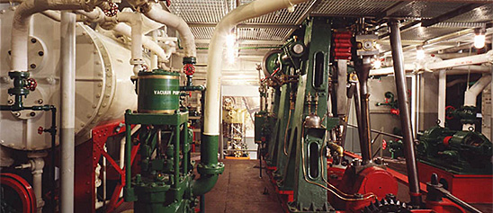
The engineering artifacts document the history of civil and mechanical engineering in the United States. So far, the Museum has declined to collect dams, skyscrapers, and bridges, but these and other important engineering achievements are preserved through blueprints, drawings, models, photographs, sketches, paintings, technical reports, and field notes.

This is a low gas pressure, atmospheric air pressure, multijet, multiunit type of gas burner. It consists of a number of tubes within which the gas and air are mixed, heated, and ignited.
Description
This is a low gas pressure, atmospheric air pressure, multijet, multiunit type of gas burner. It consists of a number of tubes within which the gas and air are mixed, heated, and ignited. The tubes are holes formed in a thick refractory block that protects the gas manifold from the heat of the flame and provides an incandescent zone at the mouth of each tube, which heats and ignites the mixture. The gas is supplied under pressure to each tube from a resulting agitation and mixing of the gas and air within the tube. The air is drawn into the furnace through the tube by reason of the draft within the furnace. It is claimed that the burner effects complete combustion of the fuel with only 12 to 14 percent of the air in excess of that theoretically required for complete combustion.
This burner has eight burner tubes and consists of three principal parts, the refractory block in which the tubes are formed, the gas manifold, and the air damper. The gas manifold is a rectangular box that fits against the back of the tube block and has cylindrical openings in line with the tubes. In each tube opening in the manifold are cast the fours jets through which gas is supplied to the tube. The damper is a hinged door that fits over the back of the gas manifold and controls the flow of air into the air tubes.
This burner, which is 11 inches square, burns 1,500 cubic feet of natural gas an hour at 3-ounce gas pressure, or 2,400 cubic feet at 10-ounce pressure.
Reference:
This description comes from the 1939 Catalog of the Mechanical Collections of the Division of Engineering United States Museum Bulletin 173 by Frank A. Taylor.
Location
Currently not on view
ID Number
MC.310203
catalog number
310203
accession number
112298
This model was submitted to the U.S. Patent Office with the application for Patent no.
Description
This model was submitted to the U.S. Patent Office with the application for Patent no. 168623, issued to Gottlieb Daimler, of Muelheim-on-the-Rhine, Prussia, October 11, 1875.
Daimler, who was managing director of Otto’s Gas Moteren Fabric, 1872-1882, introduced this engine as an improvement over the Langen and Otto engine of 1866. The engine is of the double-acting, free-piston, atmospheric type.
A water-jacket cylinder open to the atmosphere at both ends contains a working piston and two other pistons, one on each side of the working piston, which are loose or unconnected and operate in conjunction with the working piston in the following manner: With the working piston at the end of its back stroke, a charge of gas and air is drawn into the space between it and the front loose piston and is exploded. The said loose piston is thrown to the front end of the cylinder (without doing work) where it is held by a wedge device, whereupon a partial vacuum being formed in the cylinder by the expansion and cooling of the gaseous products of combustion, the working piston will by atmospheric pressure be caused to perform its forward stroke, the back loose piston traveling with it. On approaching the front loose piston the back loose piston is arrested in its motion while the working piston completes its stroke, moving close up to the front loose piston and expelling the products of combustion from between them, while at the same time a charge of gas and air is drawn into the space formed between the working piston and the back loose piston. On the charge being exploded, the back loose piston is thrown to the back end of the cylinder and the working piston performs its back stroke, together with the front loose piston, and the operation is repeated as above described.
Reference:
This description comes from the 1939 Catalog of the Mechanical Collections of the Division of Engineering United States Museum Bulletin 173 by Frank A. Taylor.
Location
Currently not on view
date made
1875
patent date
1875-10-11
inventor
Daimler, Gottlieb W.
ID Number
MC.308689
catalog number
308689
accession number
89797
patent number
168,623
This pencil was grouped with a number of pencils found in the pocket of a tool belt used by Jillian Gross while working for Habitat for Humanity, a not-for-profit, non-government organization advocating affordable housing around the world.
Description
This pencil was grouped with a number of pencils found in the pocket of a tool belt used by Jillian Gross while working for Habitat for Humanity, a not-for-profit, non-government organization advocating affordable housing around the world. Carpenter pencils have two wide, flat sides to keep them from rolling. The graphite core is generally wide and flat, making it easy to mark course materials when using the flat side while using the thinner side for precision marks.
When Hurricane Katrina struck the Gulf Coast in August 2005, Jillian Gross had worked with Habitat for Humanity for three years learning woodworking and house-building skills. Groups such as Habitat for Humanity marshaled volunteers, tools and lumber to step in when it became clear that normal avenues of housing assistance were overwhelmed.
In November 2005, Habitat for Humanity launched “America Builds on the National Mall,” a demonstration house-building marathon in Washington, D.C. in which the basic components of 51 homes were assembled within a week and shipped to the Gulf Coast. Upon completion of the project Ms. Gross, one of the house building leaders during this event, donated her tool belt, tools and protective wear to the Smithsonian Institution.
Location
Currently not on view
ID Number
2005.0276.27
catalog number
2005.0276.27
accession number
2005.0276
The glazier knife has multiple uses: scraping, roller squeegee, spackle spreader, crack or crevice cleaner and can opener. Made by Warner Manufacturing Company, Plymouth, Minnesota, makers of hand and edge tools and light equipment.
Description
The glazier knife has multiple uses: scraping, roller squeegee, spackle spreader, crack or crevice cleaner and can opener. Made by Warner Manufacturing Company, Plymouth, Minnesota, makers of hand and edge tools and light equipment. It was used by Jillian Gross while working for Habitat for Humanity, a not-for-profit, non-government organization advocating affordable housing around the world.
When Hurricane Katrina struck the Gulf Coast in August 2005, Jillian Gross had worked with Habitat for Humanity for three years learning woodworking and house-building skills. Groups such as Habitat for Humanity marshaled volunteers, tools and lumber to step in when it became clear that normal avenues of housing assistance were overwhelmed.
In November 2005, Habitat for Humanity launched “America Builds on the National Mall,” a demonstration house-building marathon in Washington, D.C. in which the basic components of 51 homes were assembled within a week and shipped to the Gulf Coast. Upon completion of the project Ms. Gross, one of the house building leaders during this event, donated her tool belt, tools and protective wear to the Smithsonian Institution. The glazier knife was kept in the pocket of a tool belt.
Location
Currently not on view
ID Number
2005.0276.25
catalog number
2005.0276.25
accession number
2005.0276
A utility knife is a general purpose cutting tool. This knife has a retractable steel blade and a red painted aluminum holder. It was made in China for the American home improvement store Lowe's Task Force brand.
Description
A utility knife is a general purpose cutting tool. This knife has a retractable steel blade and a red painted aluminum holder. It was made in China for the American home improvement store Lowe's Task Force brand. The manufacturering company that produces their tools can vary from year to year. The knife was used by Jillian Gross while working for Habitat for Humanity, a not-for-profit, non-government organization advocating affordable housing around the world.
When Hurricane Katrina struck the Gulf Coast in August 2005, Jillian Gross had worked with Habitat for Humanity for three years learning woodworking and house-building skills. Groups such as Habitat for Humanity marshaled volunteers, tools and lumber to step in when it became clear that normal avenues of housing assistance were overwhelmed.
In November 2005, Habitat for Humanity launched “America Builds on the National Mall,” a demonstration house-building marathon in Washington, D.C. in which the basic components of 51 homes were assembled within a week and shipped to the Gulf Coast. Upon completion of the project Ms. Gross, one of the house building leaders during this event, donated her tool belt, tools and protective wear to the Smithsonian Institution. The notebook was kept in the pocket of a tool belt.
Location
Currently not on view
ID Number
2005.0276.21
catalog number
2005.0276.21
accession number
2005.0276
This pen was used by Jillian Gross while working for Habitat for Humanity, a not-for-profit, non-government organization advocating affordable housing around the world.
Description
This pen was used by Jillian Gross while working for Habitat for Humanity, a not-for-profit, non-government organization advocating affordable housing around the world. This red transparent plastic pen has a rubber grip, retractable point and pocket clip.
When Hurricane Katrina struck the Gulf Coast in August 2005, Jillian Gross had worked with Habitat for Humanity for three years learning woodworking and house-building skills. Groups such as Habitat for Humanity marshaled volunteers, tools and lumber to step in when it became clear that normal avenues of housing assistance were overwhelmed.
In November 2005, Habitat for Humanity launched “America Builds on the National Mall,” a demonstration house-building marathon in Washington, D.C. in which the basic components of 51 homes were assembled within a week and shipped to the Gulf Coast. Upon completion of the project Ms. Gross, one of the house building leaders during this event, donated her tool belt, tools and protective wear to the Smithsonian Institution. The pen was kept with her notebook.
Location
Currently not on view
ID Number
2005.0276.36
catalog number
2005.0276.36
accession number
2005.0276
This general purpose or common hammer is used for pounding nails and prying nails or other light material such as molding. The hammer is all one forged steel piece with a blue nylon grip. It has a smooth striking face and straight claw.
Description
This general purpose or common hammer is used for pounding nails and prying nails or other light material such as molding. The hammer is all one forged steel piece with a blue nylon grip. It has a smooth striking face and straight claw. It was used by Jillian Gross while working for Habitat for Humanity, a not-for-profit, non-government organization advocating affordable housing around the world.
When Hurricane Katrina struck the Gulf Coast in August 2005, Jillian Gross had worked with Habitat for Humanity for three years learning woodworking and house-building skills. Groups such as Habitat for Humanity marshaled volunteers, tools and lumber to step in when it became clear that normal avenues of housing assistance were overwhelmed.
In November 2005, Habitat for Humanity launched “America Builds on the National Mall,” a demonstration house-building marathon in Washington, D.C. in which the basic components of 51 homes were assembled within a week and trucked off to the Gulf Coast. Upon completion of the project Ms. Gross, one of the house building leaders during this event, donated her tool belt, tools and protective wear to the Smithsonian Institution.
Location
Currently not on view
maker
Estwing
ID Number
2005.0276.10
catalog number
2005.0276.10
accession number
2005.0276
This nail puller, also referred to as a cat's paw, is designed to pull out nails and for light demolition. The length has a hexagonal shape, each end is curved, tapered and slotted.
Description
This nail puller, also referred to as a cat's paw, is designed to pull out nails and for light demolition. The length has a hexagonal shape, each end is curved, tapered and slotted. It was used by Jillian Gross while working for Habitat for Humanity, a not-for-profit, non-government organization advocating affordable housing around the world.
When Hurricane Katrina struck the Gulf Coast in August 2005, Jillian Gross had worked with Habitat for Humanity for three years learning woodworking and house-building skills. Groups such as Habitat for Humanity marshaled volunteers, tools and lumber to step in when it became clear that normal avenues of housing assistance were overwhelmed.
In November 2005, Habitat for Humanity launched “America Builds on the National Mall,” a demonstration house-building marathon in Washington, D.C. in which the basic components of 51 homes were assembled within a week and shipped to the Gulf Coast. Upon completion of the project Ms. Gross, one of the house building leaders during this event, donated her tool belt, tools and protective wear to the Smithsonian Institution.
Location
Currently not on view
ID Number
2005.0276.12
catalog number
2005.0276.12
accession number
2005.0276
This short flat pry bar is for pulling nails and performing light work such as prying paneling or molding. Both ends are curved and slotted.
Description
This short flat pry bar is for pulling nails and performing light work such as prying paneling or molding. Both ends are curved and slotted. It was used by Jillian Gross while working for Habitat for Humanity, a not-for-profit, non-government organization advocating affordable housing around the world.
When Hurricane Katrina struck the Gulf Coast in August 2005, Jillian Gross had worked with Habitat for Humanity for three years learning woodworking and house-building skills. Groups such as Habitat for Humanity marshaled volunteers, tools and lumber to step in when it became clear that normal avenues of housing assistance were overwhelmed.
In November 2005, Habitat for Humanity launched “America Builds on the National Mall,” a demonstration house-building marathon in Washington, D.C. in which the basic components of 51 homes were assembled within a week and shipped to the Gulf Coast. Upon completion of the project Ms. Gross, one of the house building leaders during this event, donated her tool belt, tools and protective wear to the Smithsonian Institution.
Location
Currently not on view
ID Number
2005.0276.19
catalog number
2005.0276.19
accession number
2005.0276
This belt clip was distributed in a Swanson speed square package. The clip hooks on to a belt and holds a speed square or other tools.
Description
This belt clip was distributed in a Swanson speed square package. The clip hooks on to a belt and holds a speed square or other tools. It was used by Jillian Gross while working for Habitat for Humanity, a not-for-profit, non-government organization advocating affordable housing around the world.
When Hurricane Katrina struck the Gulf Coast in August 2005, Jillian Gross had worked with Habitat for Humanity for three years learning woodworking and house-building skills. Groups such as Habitat for Humanity marshaled volunteers, tools and lumber to step in when it became clear that normal avenues of housing assistance were overwhelmed.
In November 2005, Habitat for Humanity launched “America Builds on the National Mall,” a demonstration house-building marathon in Washington, D.C. in which the basic components of 51 homes were assembled within a week and shipped to the Gulf Coast. Upon completion of the project Ms. Gross, one of the house building leaders during this event, donated her tool belt, tools and protective wear to the Smithsonian Institution.
Location
Currently not on view
ID Number
2005.0276.17
catalog number
2005.0276.17
accession number
2005.0276
This short, flat pry bar is for pulling nails and performing light work such as prying paneling or molding. Both ends are curved and slotted.
Description
This short, flat pry bar is for pulling nails and performing light work such as prying paneling or molding. Both ends are curved and slotted. It was used by Jillian Gross while working for Habitat for Humanity, a not-for-profit, non-government organization advocating affordable housing around the world.
When Hurricane Katrina struck the Gulf Coast in August 2005, Jillian Gross had worked with Habitat for Humanity for three years learning woodworking and house-building skills. Groups such as Habitat for Humanity marshaled volunteers, tools and lumber to step in when it became clear that normal avenues of housing assistance were overwhelmed.
In November 2005, Habitat for Humanity launched “America Builds on the National Mall,” a demonstration house-building marathon in Washington, D.C. in which the basic components of 51 homes were assembled within a week and shipped to the Gulf Coast. Upon completion of the project Ms. Gross, one of the house building leaders during this event, donated her tool belt, tools and protective wear to the Smithsonian Institution.
Location
Currently not on view
ID Number
2005.0276.18
catalog number
2005.0276.18
accession number
2005.0276
This Märklin No. 5 toy steam engine was built by the Märklin Manufacturing Company of Göppingen, Germany during the early 20th century. This toy steam engine consists of an externally fired horizontal brass boiler on top of a simulated brick firebox and chimney.
Description (Brief)
This Märklin No. 5 toy steam engine was built by the Märklin Manufacturing Company of Göppingen, Germany during the early 20th century. This toy steam engine consists of an externally fired horizontal brass boiler on top of a simulated brick firebox and chimney. The horizontal slide valve cylinder engine drives a flywheel with slip-eccentric reversing gear. The boiler and engine are mounted on a tinplate base.
The Märklin Company was established in 1859 in the town of Göppingen, Germany by tin smith Theodor Friedrich Wilhelm Märklin. Märklin began his business with the production of tin doll houses, but the company soon began producing a variety of tinplate and metal items, eventually specializing in toys that included steam engines such as this one.
Location
Currently not on view
date made
ca 1950
ID Number
MC.322911
catalog number
322911
accession number
220719
This model was submitted to the U.S. Patent Office with the application for the patent issued to Charles Miller, of Belleville, Illinois, May 3, 1859, no. 23852.The engine has two oval pistons or cams each running in a separate circular cylinder or casing.
Description
This model was submitted to the U.S. Patent Office with the application for the patent issued to Charles Miller, of Belleville, Illinois, May 3, 1859, no. 23852.
The engine has two oval pistons or cams each running in a separate circular cylinder or casing. Sliding abutments in the casing bearing on the edges of the cams direct the steam in the forward direction around the casing. Admission of steam is controlled by two flat slide valves working in steam chests on top of the casing. The valves are operated by two eccentrics on the engine shaft. The engine is reversible.
Reference:
This description comes from the 1939 Catalog of the Mechanical Collections of the Division of Engineering United States Museum Bulletin 173 by Frank A. Taylor.
Location
Currently not on view
date made
1859
patent date
1859-05-03
inventor
Miller, Charles
ID Number
ER.251294
accession number
48865
catalog number
251294
patent number
23,852
This toy motor was manufactured by the Hess Company in Nuremburg, Germany during the early 20th century. The “J.L.H.” makers mark on the base of the toy dates the motor to between 1906 and 1930, when John Leonard Hess took over the company.
Description (Brief)
This toy motor was manufactured by the Hess Company in Nuremburg, Germany during the early 20th century. The “J.L.H.” makers mark on the base of the toy dates the motor to between 1906 and 1930, when John Leonard Hess took over the company. This type of friction-inertia motor was marketed as the Dynamobil. The motor is a crank operated friction-inertia toy. The winding of the crank builds up inertia and when the switch is turned on, the engine spins its axel, which would power machine accessories connected to the engine either directly or through a line shaft.
Location
Currently not on view
ID Number
MC.329043
catalog number
329043
accession number
278175
This model was submitted to the U.S. Patent Office with the application for the patent issued to Francis B. Stevens, November 3, 1863, no.
Description
This model was submitted to the U.S. Patent Office with the application for the patent issued to Francis B. Stevens, November 3, 1863, no. 40510.
The condenser represented in the model consists of a large vertical cylinder and pump plunger with various connected chambers designed to function as a condenser, a condenser air pump, and feed-water hot well and heater.
The invention “consists in simplifying the apparatus that condenses the steam discharged by the first eduction from the cylinder of a condensing steam engine by closing the hot well of the engine against the atmosphere and by keeping a portion of the space of the hot well free from water, and by delivering the steam discharged from the cylinder by the first eduction into the hot well, so that it may be condensed or partially condensed by the water delivered by the air-pump into the hot well.” The hot well is thus made “to act also as an additional condenser and dispense altogether with an additional air pump to draw the water from the additional condenser.”
Reference:
This description comes from the 1939 Catalog of the Mechanical Collections of the Division of Engineering United States Museum Bulletin 173 by Frank A. Taylor.
Location
Currently not on view
date made
1863
patent date
1863-11-03
inventor
Stevens, Francis B.
ID Number
MC.309238
catalog number
309238
accession number
89797
patent number
40,510
date made
1952
SS United States built and launched
1952
naval architect of SS United States
Gibbs, William Francis
painter
Wendell, Raymond John
ID Number
TR.336767.162
catalog number
336767.162
accession number
1978.2219
This is a rectangular bucket divided by a central splitter edge into two hollow semicylindrical compartments. The bucket is designed to receive and divide the jet upon the slitter edge and direct the water to either side, discharging at the sides.
Description
This is a rectangular bucket divided by a central splitter edge into two hollow semicylindrical compartments. The bucket is designed to receive and divide the jet upon the slitter edge and direct the water to either side, discharging at the sides. No provision is made for the flow of water in a radial direction along bucket, and the outer end of the bucket makes sharp angles with the sides and bottom. The extreme lip of the bucket is very slightly depressed, suggesting the notched lip developed later. The back of the bucket is provided with lugs, which slip over the rim of the wheel center to which it is attached by the bolts passing through the lugs and rim parallel to the shaft. The bucket is made of cast iron, measures about 11.5 inches wide, and weighs 30 pounds. This bucket was made about 1901.
Reference:
This description comes from the 1939 Catalog of the Mechanical Collections of the Division of Engineering United States Museum Bulletin 173 by Frank A. Taylor.
Location
Currently not on view
date made
ca 1901
ID Number
MC.310386
catalog number
310386
accession number
117363
The Weeden Manufacturing Company of New Bedford, Massachusetts, manufactured the Weeden “Favorite” engine from around 1880 until the middle of the 1890s. The vertical boiler powers a vertical engine, with built-in fuel tank for a self-contained burner.
Description (Brief)
The Weeden Manufacturing Company of New Bedford, Massachusetts, manufactured the Weeden “Favorite” engine from around 1880 until the middle of the 1890s. The vertical boiler powers a vertical engine, with built-in fuel tank for a self-contained burner. The “Favorite” engine was sold alone or with attachments like a force pump or pile driver.
The Weeden Manufacturing Company was founded in New Bedford, Massachusetts by William M. Weeden in the early 1880s, originally producing a variety of tinplate household items. In 1884 it introduced the Weeden No. 1 Steam engine as “a new and great premium for boys” who were subscribers to the Youth’s Companion magazine. Weeden made over a hundred different models of toy steam engines until the company ceased operations in 1952.
Location
Currently not on view
date made
late 19th century
ID Number
MC.328955
catalog number
328955
accession number
278175
date made
1952
SS United States built and launched
1952
naval architect of SS United States
Gibbs, William Francis
painter
Wendell, Raymond John
ID Number
TR.336767.161
catalog number
336767.161
accession number
1978.2219
This model was submitted to the U.S. Patent Office with the application for the patent issued to Henry R. Worthington, of New York, New York, June 20, 1871, no.
Description
This model was submitted to the U.S. Patent Office with the application for the patent issued to Henry R. Worthington, of New York, New York, June 20, 1871, no. 116131.
The model is a relief panel showing a section through the two steam cylinders of a duplex pump arranged to use steam at boiler pressure in one steam cylinder of small diameter, expand the exhaust steam in a receiver of much larger volume than the small cylinder, and use the steam at low pressure in a second cylinder of larger diameter. This arrangement was devised to permit the use of steam expansively in a duplex pump without the use of two compound cylinders, as was formerly the method.
Reference:
This description comes from the 1939 Catalog of the Mechanical Collections of the Division of Engineering United States Museum Bulletin 173 by Frank A. Taylor.
Location
Currently not on view
date made
1871
patent date
1871-06-20
inventor
Worthington, Henry R.
ID Number
ER.308681
accession number
89797
catalog number
308681
patent number
116,131
This toy steam engine was made by the Märklin Company during the early 20th century. The engine consists of a firebox that is painted to simulate brickwork with a green chimney stack.
Description (Brief)
This toy steam engine was made by the Märklin Company during the early 20th century. The engine consists of a firebox that is painted to simulate brickwork with a green chimney stack. The horizontal boiler has a steam whistle and throttle that is connected to a horizontal slide valve engine that powers a flywheel. The generator was added by hobbyist Greville Bathe at a later date.
The Märklin Company was established in 1859 in the town of Göppingen, Germany by tin smith Theodor Friedrich Wilhelm Märklin. Märklin began his business with the production of tin doll houses, but the company soon began producing a variety of tinplate and metal items, eventually specializing in toys that included steam engines such as this one.
Location
Currently not on view
ID Number
MC.329032
catalog number
329032
accession number
278175
This toy steam engine was made by an unknown German maker around the early 20th century. The toy consists of a vertical boiler, vertical engine, and flywheel.
Description (Brief)
This toy steam engine was made by an unknown German maker around the early 20th century. The toy consists of a vertical boiler, vertical engine, and flywheel. The chimney stack is in the shape of a hexagon.
Live steam toys enjoyed a period of popularity from the 1880s until the 1930s. The miniature steam engines were marketed as both toys and instructive devices that mimicked full-scale steam-powered machines and allowed every boy and girl to be their own engineer. In toy steam engines, a heating source is introduced into the firebox below the boiler (early toys used lit wicks fueled by denatured alcohol, later toys used electricity) which heated the water to produce the steam pressure that ran the engine. A variety of accessories could be powered by the engine; attachments included windmills, pumps, grinders, and electric lights.
Location
Currently not on view
date made
early 20th century
ID Number
MC.328983
catalog number
328983
accession number
278175
This model was submitted to the U.S. Patent Office with the application for the patent issued to J. and F. M. Cottle, October 21, 1879, no.
Description
This model was submitted to the U.S. Patent Office with the application for the patent issued to J. and F. M. Cottle, October 21, 1879, no. 220751.
This mill has a double-rimmed steel wind wheel made up of small wedge-shaped vanes, which are removable to permit regulation of the power of the mill. The wind wheel cannot be swung out of its position, but the shaft is carried in sliding bearings so that the gear on the shaft can be disengaged to let the wheel run free. It is equipped with a selective gear transmission. The model shows the mill attached to the bucket chain of a well.
Reference:
This description comes from the 1939 Catalog of the Mechanical Collections of the Division of Engineering United States Museum Bulletin 173 by Frank A. Taylor.
Location
Currently not on view
date made
1879
patent date
1879-10-21
inventor
Cottle, Zorah
Cottle, F. M.
ID Number
ER.309131
accession number
89797
catalog number
309131
patent number
220,751
This model was submitted to the U.S. Patent Office with the application for the patent issued to George H. Corliss, August 8, 1882, no.
Description
This model was submitted to the U.S. Patent Office with the application for the patent issued to George H. Corliss, August 8, 1882, no. 262209.
The model represents a flyball governor in which the motion of the slide, owing to a change in the speed of the engine to which the governor is attached, not only changes the position of the cut-off or throttle devices to regulate the speed of the engine but also changes the gear ratio between the engine and the governor to change the speed of the governor relative to the speed of the engine.
When the governor speed is increased by an increase in the speed of the engine, the balls rise and communicate motion to a slide, which, in turn, affects the throttle or cut-off to return the engine to its lower speed. At the same time the motion of the slide shifts a friction roller on its driving disk so that the governor speed is increased relative to the engine causing an additional motion of the slide in the same direction. As a result, the governor slide is given a greater motion for a given change in speed than would otherwise result.
Reference:
This description comes from the 1939 Catalog of the Mechanical Collections of the Division of Engineering United States Museum Bulletin 173 by Frank A. Taylor.
Location
Currently not on view
date made
1882
patent date
1882-08-08
inventor
Corliss, George H.
ID Number
MC.308715
catalog number
308715
accession number
89797
patent number
262,209

Our collection database is a work in progress. We may update this record based on further research and review. Learn more about our approach to sharing our collection online.

If you would like to know how you can use content on this page, see the Smithsonian's Terms of Use. If you need to request an image for publication or other use, please visit Rights and Reproductions.