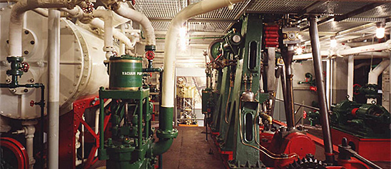
Engineering, Building, and Architecture

Not many museums collect houses. The National Museum of American History has four, as well as two outbuildings, 11 rooms, an elevator, many building components, and some architectural elements from the White House. Drafting manuals are supplemented by many prints of buildings and other architectural subjects. The breadth of the museum's collections adds some surprising objects to these holdings, such as fans, purses, handkerchiefs, T-shirts, and other objects bearing images of buildings.

The engineering artifacts document the history of civil and mechanical engineering in the United States. So far, the Museum has declined to collect dams, skyscrapers, and bridges, but these and other important engineering achievements are preserved through blueprints, drawings, models, photographs, sketches, paintings, technical reports, and field notes.

This toy steam engine consists of a vertical boiler and horizontal slide valve engine. The museum’s catalogue records indicate that the toy was manufactured in the late 19th century, possibly by the J.E.
Description (Brief)
This toy steam engine consists of a vertical boiler and horizontal slide valve engine. The museum’s catalogue records indicate that the toy was manufactured in the late 19th century, possibly by the J.E. Stevens Manufacturing Company or the Buckman Manufacturing Company, but no manufacturing marks can be seen on the object.
Live steam toys enjoyed a period of popularity from the 1880s until the 1930s. The miniature steam engines were marketed as both toys and instructive devices that mimicked full-scale steam-powered machines and allowed every boy and girl to be their own engineer. In toy steam engines, a heating source is introduced into the firebox below the boiler (early toys used lit wicks fueled by denatured alcohol, later toys used electricity) which heated the water to produce the steam pressure that ran the engine. A variety of accessories could be powered by the engine; attachments included windmills, pumps, grinders, and electric lights.
Location
Currently not on view
date made
late 19th century
ID Number
MC.328981
catalog number
328981
accession number
278175
The Bing Company of Bavaria, Germany manufactured this toy steam engine during the early 20th century. The horizontal boiler has a steam whistle and sight glass above a black firebox with a simulated brickwork chimney.
Description (Brief)
The Bing Company of Bavaria, Germany manufactured this toy steam engine during the early 20th century. The horizontal boiler has a steam whistle and sight glass above a black firebox with a simulated brickwork chimney. The boiler powers an orange horizontal slide valve engine and flywheel. Everything is mounted on a tin base that measures 9.25 by 9.5 inches.
The Gebrüder Bing (Bing Brothers) toy company was founded in Nuremburg, Germany by Adolf and Ignatz Bing in 1863 and operated until 1932. The company was renamed Bing Werke (Bing Works) in 1918 when Ignatz Bing died. While very successful from 1863 until 1912, World War I created an unfavorable export market for German products, and the hard post-war years caused additional financial hardships. The harsh political climate in Germany forced the Jewish Bing family to flee to England in 1932, and Bing’s assets were acquired by rival toy company Bub in 1933.
Location
Currently not on view
date made
20th century
ID Number
MC.328991
catalog number
328991
accession number
278175
This model was submitted to the U.S. Patent Office with the application for the patent issued to Joseph Wotapek, of New York, New York, May 6, 1884, no.
Description
This model was submitted to the U.S. Patent Office with the application for the patent issued to Joseph Wotapek, of New York, New York, May 6, 1884, no. 298329; assigned to the Nation Manufacturing Co.
The improvement involved in this injector is the use of a nozzle holder by which the scale-incrusted nozzle or tube of the injector may be easily removed to permit cleaning. The holder is threaded into the shell of the injector from which it and the tube are drawn by unscrewing the bolder. The holder turns independently of the tube so that the tube itself is not subjected to torsion when being withdrawn from the shell.
Reference:
This description comes from the 1939 Catalog of the Mechanical Collections of the Division of Engineering United States Museum Bulletin 173 by Frank A. Taylor.
Location
Currently not on view
date made
1884
patent date
1884-05-06
inventor
Wotapek, Joseph
ID Number
MC.309181
catalog number
309181
patent number
298,329
accession number
89797
This model was submitted to the U.S. Patent Office with the application for the patent issued to John Warren, of Detroit, Michigan, April 20, 1880, no.
Description
This model was submitted to the U.S. Patent Office with the application for the patent issued to John Warren, of Detroit, Michigan, April 20, 1880, no. 226813.
The motor represented is of the class intended to operate light machinery such as a phonograph but differs from most of the class in that it employs a spiral spring instead of the usual coil spring. It converts the rectilinear motion of the spring into rotary motion and equalizes the varying tension of the spring.
The free end of the spring carries a nut that engages in a spiral-grooved motor shaft, which revolves at the axis of the spring. A hand crank, worm, and worm wheel are used to compress the spring by turning the shaft in the reverse direction. The power is taken from a bevel gear on the shaft. A ball nut, which employs a ball to follow in the groove of the shaft, is used because an ordinary nut would not work in the groove of varying pitch. The varying pitch is used to compensate for the varying tension of the spring.
Reference:
This description comes from the 1939 Catalog of the Mechanical Collections of the Division of Engineering United States Museum Bulletin 173 by Frank A. Taylor.
Location
Currently not on view
date made
1880
patent date
1880-04-20
inventor
Warren, John
ID Number
MC.308835
catalog number
308835
accession number
89797
patent number
226,813
This model was submitted to the U.S. Patent Office with its application for Patent no. 217758, issued to James M. Whiting, of Providence, Rhode Island, July 22, 1879.This is an example of combined air and steam engines, many designs of which have been proposed and built.
Description
This model was submitted to the U.S. Patent Office with its application for Patent no. 217758, issued to James M. Whiting, of Providence, Rhode Island, July 22, 1879.
This is an example of combined air and steam engines, many designs of which have been proposed and built. In this engine the use of steam is intended to reduce the bulk of the heated air required to operate an engine of a given capacity and consequently reduce the size of the engine.
The model shows a vertical fire-tube steam boiler of ordinary construction above the tubes of which is placed a hollow drum that is heated by the hot gases from the boiler. There is also a small steam pump and a vertical high-speed steam engine of the slide-valve type. Steam from the boiler is mixed with the heated air in the upper drum, and the mixture of heated air and steam is led directly to the engine and expanded. The air pump supplies air to the heated drum.
Reference:
This description comes from the 1939 Catalog of the Mechanical Collections of the Division of Engineering United States Museum Bulletin 173 by Frank A. Taylor.
Location
Currently not on view
date made
1879
patent date
1879-07-22
inventor
Whiting, James M.
ID Number
ER.251285
accession number
48865
catalog number
251285
patent number
217,758
Shaeffer & Budenberg manufactured this steam engine indicator.
Description
Shaeffer & Budenberg manufactured this steam engine indicator. It consists of a large brass piston with a single groove; a vented brass cylinder; an internal, single wound spring, which can be changed; a large drum with a spiral spring and single record; and a heavy brass stylus. Accompanying the indicator is a wooden box with three scales and a wooden ram rod.
An engine indicator is an instrument for graphically recording the pressure versus piston displacement through an engine stroke cycle. Engineers use the resulting diagram to check the design and performance of the engine.
A mechanical indicator consists of a piston, spring, stylus, and recording system. The gas pressure of the cylinder deflects the piston and pushes against the spring, creating a linear relationship between the gas pressure and the deflection of the piston against the spring. The deflection is recorded by the stylus on a rotating drum that is connected to the piston. Most indicators incorporate a mechanical linkage to amplify the movement of the piston to increase the scale of the record.
When the ratio of the frequency of the pressure variation to the natural frequency of the system is small, then the dynamic deflection is equal to the static deflection. To design a system with a high natural frequency, the mass of the piston, spring, stylus, and mechanical linkage must be small, but the stiffness of the spring must be high. The indicator is subjected to high temperatures and pressures and rapid oscillations, imposing a limitation on the reduction in mass. Too stiff a spring will result in a small displacement of the indicator piston and a record too small to measure with accuracy. Multiplication of the displacement will introduce mechanical ad dynamic errors.
The parameters of the problem for designing an accurate and trouble free recorder are such that there is no easy or simple solution. Studying the variety of indicators in the collection shows how different inventors made different compromises in their designs.
Location
Currently not on view
maker
Schaeffer and Bundenberg Manufacturing Company
ID Number
1981.0217.03
accession number
1981.0217
catalog number
1981.0217.03
This model was submitted to the U.S. Patent Office with the application for the patent issued to Adam S. Cameron, of New York, New York, November 10, 1874, no.
Description
This model was submitted to the U.S. Patent Office with the application for the patent issued to Adam S. Cameron, of New York, New York, November 10, 1874, no. 156769.
This invention relates to a design of pump valves so controlled by spindles and guides that the necessity of central bearings in the valve seat is avoided, leaving a clear circular opening for the passage of the fluid being pumped.
The model represents a valve chest of a pump cylinder equipped with four valves arranged in pairs, in which one valve is located above the other. In each pair the valve stem of the upper valve projects upward into a hollow plug in the top of the valve chest and downward into a socket in the lower valve. The socket of the lower valve extends downward into a hollow plug or guide in the bottom of the valve chest. Both valves are spring closed and the lower valve is free to move independently of the upper valve.
Reference:
This description comes from the 1939 Catalog of the Mechanical Collections of the Division of Engineering United States Museum Bulletin 173 by Frank A. Taylor.
Location
Currently not on view
date made
1874
patent date
1874-11-10
inventor
Cameron, Adam S.
ID Number
ER.308686
accession number
89797
catalog number
308686
patent number
156,769
This toy engine consists of a vertical duplex oscillating engine that consists of some homemade parts and some parts from the J.E. Stevens Company. The donor of this item, Greville Bathe, was a machinist who would fashion his own parts to complete engines and models.
Description (Brief)
This toy engine consists of a vertical duplex oscillating engine that consists of some homemade parts and some parts from the J.E. Stevens Company. The donor of this item, Greville Bathe, was a machinist who would fashion his own parts to complete engines and models. The engine could be powered by an external boiler.
Location
Currently not on view
ID Number
MC.329016
catalog number
329016
accession number
278175
associated institution
Faesch & Piccard
ID Number
EM.315850
catalog number
315850
accession number
221414
This model was filed with the application to the U.S. Patent Office for the patent issued to Lucius J. Knowles, of Worcester, Massachusetts, April 1, 1879, no.
Description
This model was filed with the application to the U.S. Patent Office for the patent issued to Lucius J. Knowles, of Worcester, Massachusetts, April 1, 1879, no. 231823.
The model represents the steam cylinders of a duplex pump fitted with what the inventor calls auxiliary engines to operate the valves of each cylinder when it is desired to use one cylinder of a duplex pump without the other. Actually the piston of the auxiliary engine is the valve of the main cylinder and the invention is in effect a one cylinder “simplex” pump with steam-actuated valve. This is one of the earliest uses of the steam-actuated valve for steam pumps.
The auxiliary cylinder forms the steam chest and valve ports of the main cylinder while the auxiliary piston acts as the valve. The auxiliary piston has its own valve system, which consists of ports in the auxiliary cylinder wall connected to the main steam passages and so located that they will register with openings in the auxiliary piston when the auxiliary piston is given a slight twist at the end of the main piston’s stroke. These openings connect to passages in the auxiliary cylinder to cause the auxiliary piston to move to the other end of the cylinder and so reverse the stroke of the main piston.
Lucius James Knowles (July 2, 1819 – February 26, 1884) originated and developed the Knowles Steam Pump Co. and the L. J. Knowles & Brother Loom Works at Warren, Massachusetts, and Worcester, Massachusetts, both of which became leading organizations in their respective fields. The Knowles steam pump was one of the best known of the direct-acting pumps, and Knowles is recognized as having contributed much to the final development and refinement of the device. He was one of the first to take up and develop the steam-actuated valve and received several patents for his inventions of improvements in valves.
Reference:
This description comes from the 1939 Catalog of the Mechanical Collections of the Division of Engineering United States Museum Bulletin 173 by Frank A. Taylor.
Location
Currently not on view
date made
1879
patent date
1879-04-01
inventor
Knowles, Lucius J.
ID Number
ER.309250
accession number
89797
patent number
213,823
catalog number
309250
This model was submitted to the U.S. Patent Office with the application for the patent issued to Edgar B. Brooks, of La Porte, Indiana, February 10, 1880; no.
Description
This model was submitted to the U.S. Patent Office with the application for the patent issued to Edgar B. Brooks, of La Porte, Indiana, February 10, 1880; no. 224270.
This is a nicely made brass model of an inward-flow reaction turbine having the register type of adjustable feed chutes or guide vanes and a cylinder water gate. The combination relieves the guide vanes of the function of cutting off the water when the wheel is to be stopped and makes it unnecessary that the guide vanes close perfectly, so that any looseness developed in them by wear is immaterial.
Reference:
This description comes from the 1939 Catalog of the Mechanical Collections of the Division of Engineering United States Museum Bulletin 173 by Frank A. Taylor.
Location
Currently not on view
date made
1880
patent date
1880-02-10
inventor
Brooks, Edgar B.
ID Number
MC.309689
catalog number
309689
accession number
89797
patent number
224,270
The Panama Canal links the Atlantic and Pacific Oceans through Central America.
Description
The Panama Canal links the Atlantic and Pacific Oceans through Central America. The idea of a waterway of this sort had been raised many times since Columbus's first voyage to America in 1492, but the discovery of gold in California in 1848, as well as the improvement of various technologies, brought increased urgency to the idea. The French engineers and investors who began to design and dig the Canal in the early 1880s were stopped by disease and lack of funds. Americans completed the project in 1914.
Since the 1720s, surveyors have used telesopic levels to draw level surfaces and to determine the differences in altitude between several points. This example—marked "Balbeck ainé, Bvd Montparnasse, 81. Paris" and "Canal de Panama"— was made for the French team that laid out a Panama Canal in the 1880s.
Location
Currently not on view
date made
ca 1880
maker
Balbreck ainé et fils
ID Number
PH.337071
catalog number
337071
accession number
1979.0261
This toy stamp machine steam engine accessory was manufactured by the Hess Company of Nuremburg, Germany during the early 20th century. The toy could be connected to a steam engine or Hess’s Dynamobil friction-inertia motor as a power source.
Description (Brief)
This toy stamp machine steam engine accessory was manufactured by the Hess Company of Nuremburg, Germany during the early 20th century. The toy could be connected to a steam engine or Hess’s Dynamobil friction-inertia motor as a power source. The engine would rotate the central shaft, which rotated the two cams, lifting the hammers in succession.
Location
Currently not on view
date made
ca 1900
ID Number
MC.329066
catalog number
329066
accession number
278175
This toy trip hammer was manufactured by an unknown maker during the 20th century. The trip hammer toy could be powered by connecting its pulley directly to an engine or a line shaft, and raised and struck via the cam on its central axel.Currently not on view
Description (Brief)
This toy trip hammer was manufactured by an unknown maker during the 20th century. The trip hammer toy could be powered by connecting its pulley directly to an engine or a line shaft, and raised and struck via the cam on its central axel.
Location
Currently not on view
ID Number
MC.329084
catalog number
329084
accession number
278175
This toy circular saw was manufactured by the Danish company H. Langes Legetoy around the middle of the 20th century. The circular saw is in a cast metal base painted red and could spin when its shaft was attached to an engine. H.
Description (Brief)
This toy circular saw was manufactured by the Danish company H. Langes Legetoy around the middle of the 20th century. The circular saw is in a cast metal base painted red and could spin when its shaft was attached to an engine. H. Langes Legetoy produced a variety of toy machine tools including a trip-hammer, grindstone, drill press, shaper, punch press, circular saw, tumbler, lathe, and grinder. These tools would often be arranged on a single board with a line shaft allowing all the machines to be operated simultaneously from a single power source.
Location
Currently not on view
date made
ca 1950
ID Number
MC.329079
catalog number
329079
accession number
278175
This toy steam turbine consists of a firebox and boiler in a pressed sheet metal container painted to simulate brickwork. The boiler has a sight glass and safety valve, with a steam line powering a turbine wheel made from an eggbeater gear that is connected to a second gear.
Description (Brief)
This toy steam turbine consists of a firebox and boiler in a pressed sheet metal container painted to simulate brickwork. The boiler has a sight glass and safety valve, with a steam line powering a turbine wheel made from an eggbeater gear that is connected to a second gear. A line shaft is connected to the toy’s wooden base that could be strung to the turbine and power a variety of toy machine accessories.
Location
Currently not on view
ID Number
MC.329050
catalog number
329050
accession number
278175
This toy engine consists of a vertical duplex oscillating engine with two flywheels made of brass that consists of some homemade parts and some parts from the J.E. Stevens Company.
Description (Brief)
This toy engine consists of a vertical duplex oscillating engine with two flywheels made of brass that consists of some homemade parts and some parts from the J.E. Stevens Company. The donor of this item, Greville Bathe, was a machinist who would fashion his own parts to complete engines and models. The engine could be powered by an external boiler.
Location
Currently not on view
ID Number
MC.329017
catalog number
329017
accession number
278175
This is “The Minneapolis” heat regulator that was manufactured by the Minneapolis Heat Regulator Company of Minneapolis, Minnesota in 1918.
Description
This is “The Minneapolis” heat regulator that was manufactured by the Minneapolis Heat Regulator Company of Minneapolis, Minnesota in 1918. The Minneapolis model was first manufactured around 1907, when it was first patented, and the time attachment seen in this object was sold with the Minneapolis beginning in 1912. The Minneapolis regulator had a thermometer that displayed the temperature in the room, a thermostat that kept that house at an even temperature, and a time attachment that could be set to turn on the furnace when desired. A key would be used to wind the clock, a necessary feature for the clocks that were not powered by a battery or hard wired into the house’s electrical system. The Minneapolis Heat Regulator Company merged with the Honeywell Heating Specialties in 1927 to become the Minneapolis-Honeywell Heat Regulator Company.
The ubiquity of thermostats in 21st century homes shrouds the decades of innovation, industrial design, and engineering that went into making them an everyday object in almost every home. In the early 20th century, a majority of American households still heated their homes with manually operated furnaces that required a trip down to the basement and stoking the coal fired furnace. Albert Butz’s “damper-flapper” system was patented in 1886 and allowed user to set the thermostat to a certain temperature which would open a damper to the furnace, increasing the fire and heating the house. Progressive innovations allowed for the thermostats to use gas lines, incorporate electricity, turn on at a set time, include heating and cooling in one mechanism, and even connect to the internet.
Location
Currently not on view
ID Number
2008.0011.21
accession number
2008.0011
catalog number
2008.0011.21
This model was submitted to the U.S. Patent Office with the application for the patent issued to Henry Collinson, Boston, Massachusetts, April 13, 1875, no.
Description
This model was submitted to the U.S. Patent Office with the application for the patent issued to Henry Collinson, Boston, Massachusetts, April 13, 1875, no. 161934.
The invention consists of a lid or cover with a true flat face arranged in such a manner that while being forced home against a flat seat it receives a sliding and rotating motion thereon.
The model represents an opening in a plate around which is formed a flat plane face, which forms a seat for the dish –shaped lid or cover. A curved bar of metal spans the opening over the cover and supports a threaded nut through which passes a T-handled screw by which the cover is forced against the seat. At the inner end of the screw is an eccentric head that fits in a recess in the center of the cover, so that turning the screw forces the cover against the seat and moves the center of the cover in a circle, while the friction causes the cover to rotate somewhat about its own center. The result is a combined sliding and rotating of the cover as it is forced against the seat.
Reference:
This description comes from the 1939 Catalog of the Mechanical Collections of the Division of Engineering United States Museum Bulletin 173 by Frank A. Taylor.
Location
Currently not on view
date made
1875
patent date
1875-04-13
inventor
Collinson, Henry
ID Number
ER.309219
accession number
89797
catalog number
309219
patent number
161,934
Novelty Iron Works manufactured this McNaught steam engine indicator. It consists of a brass piston and cylinder with a long steel spring above a pencil holder in the tube. It takes a direct reading with no linkage on a large drum.
Description
Novelty Iron Works manufactured this McNaught steam engine indicator. It consists of a brass piston and cylinder with a long steel spring above a pencil holder in the tube. It takes a direct reading with no linkage on a large drum. Accompanying the indicator is a box with four turn cocks and a brass wrench. The brass tube contains a spring, which may not be part of this indicator. The connector on the bottom has the wrong thread to fit the indicator. The pulley is missing.
An engine indicator is an instrument for graphically recording the pressure versus piston displacement through an engine stroke cycle. Engineers use the resulting diagram to check the design and performance of the engine.
A mechanical indicator consists of a piston, spring, stylus, and recording system. The gas pressure of the cylinder deflects the piston and pushes against the spring, creating a linear relationship between the gas pressure and the deflection of the piston against the spring. The deflection is recorded by the stylus on a rotating drum that is connected to the piston. Most indicators incorporate a mechanical linkage to amplify the movement of the piston to increase the scale of the record.
When the ratio of the frequency of the pressure variation to the natural frequency of the system is small, then the dynamic deflection is equal to the static deflection. To design a system with a high natural frequency, the mass of the piston, spring, stylus, and mechanical linkage must be small, but the stiffness of the spring must be high. The indicator is subjected to high temperatures and pressures and rapid oscillations, imposing a limitation on the reduction in mass. Too stiff a spring will result in a small displacement of the indicator piston and a record too small to measure with accuracy. Multiplication of the displacement will introduce mechanical ad dynamic errors.
The parameters of the problem for designing an accurate and trouble free recorder are such that there is no easy or simple solution. Studying the variety of indicators in the collection shows how different inventors made different compromises in their designs.
Location
Currently not on view
ID Number
1981.0217.16
accession number
1981.0217
catalog number
1981.0217.16
The model was submitted to the U.S. Patent Office with the application for the patent issued to Ila N. Moore, of Battle Creek, Michigan, June 23, 1891, no.
Description
The model was submitted to the U.S. Patent Office with the application for the patent issued to Ila N. Moore, of Battle Creek, Michigan, June 23, 1891, no. 454753.
The feature of this pump power is a piston with steam ports in the piston leading to the ends of the cylinder and a valve fitted to slide on the elongated and reduced barrel of the spool-shaped piston controlling the admission of steam through the steam ports. The object is to provide a steam pump requiring no steam chest. Steam is admitted at the center of the cylinder through two short passages connecting directly with the steam pipe. Exhaust is to a chamber on the opposite side of the cylinder. A hollow tail rod, gland, and housing form part of the exhaust passage. The piston valve, which slides on the barrel of the piston, is actuated in part by the pressure of the steam and in part by the motion of the piston. Packing rings on the outside of the valve heads operate across the steam inlet ports in the cylinder wall and the lands between grooves in the bore of the valve operate across the ports in the piston barrel.
Reference:
This description comes from the 1939 Catalog of the Mechanical Collections of the Division of Engineering United States Museum Bulletin 173 by Frank A. Taylor.
Location
Currently not on view
date made
1891
patent date
1891-06-23
inventor
Moore, Ila N.
ID Number
MC.308717
catalog number
308717
accession number
89797
patent number
454,753
The American Steam Gauge Co. of Boston, Massachusetts, manufactured this steam engine indicator, serial number 572.
Description
The American Steam Gauge Co. of Boston, Massachusetts, manufactured this steam engine indicator, serial number 572. It consists of a brass piston with one groove; a brass cylinder; an internal, single wound spring, which can be changed; a large drum with a coil spring and single record. The stylus is missing. Accompanying the indicator is a box with two small wrenches; a packet of record paper with the title on top of the Taylor Engine Company Time Card; and actual engine records on five sheets.
An engine indicator is an instrument for graphically recording the pressure versus piston displacement through an engine stroke cycle. Engineers use the resulting diagram to check the design and performance of the engine.
A mechanical indicator consists of a piston, spring, stylus, and recording system. The gas pressure of the cylinder deflects the piston and pushes against the spring, creating a linear relationship between the gas pressure and the deflection of the piston against the spring. The deflection is recorded by the stylus on a rotating drum that is connected to the piston. Most indicators incorporate a mechanical linkage to amplify the movement of the piston to increase the scale of the record.
When the ratio of the frequency of the pressure variation to the natural frequency of the system is small, then the dynamic deflection is equal to the static deflection. To design a system with a high natural frequency, the mass of the piston, spring, stylus, and mechanical linkage must be small, but the stiffness of the spring must be high. The indicator is subjected to high temperatures and pressures and rapid oscillations, imposing a limitation on the reduction in mass. Too stiff a spring will result in a small displacement of the indicator piston and a record too small to measure with accuracy. Multiplication of the displacement will introduce mechanical ad dynamic errors.
The parameters of the problem for designing an accurate and trouble free recorder are such that there is no easy or simple solution. Studying the variety of indicators in the collection shows how different inventors made different compromises in their designs.
Location
Currently not on view
ID Number
1981.0217.08
accession number
1981.0217
catalog number
1981.0217.08
The Weeden Manufacturing Company of New Bedford, Massachusetts, manufactured the Weeden No. 138 toy steam engine from 1915 until 1933. This Weeden no. 138 engine consists of a vertical steel boiler and walking beam engine mounted on grey wood, all on a steel base.
Description (Brief)
The Weeden Manufacturing Company of New Bedford, Massachusetts, manufactured the Weeden No. 138 toy steam engine from 1915 until 1933. This Weeden no. 138 engine consists of a vertical steel boiler and walking beam engine mounted on grey wood, all on a steel base. This engine has been repainted with a red and gold color scheme.
The Weeden Manufacturing Company was founded in New Bedford, Massachusetts by William M. Weeden in the early 1880s, originally producing a variety of tinplate household items. In 1884 it introduced the Weeden No. 1 Steam engine as “a new and great premium for boys” who were subscribers to the Youth’s Companion magazine. Weeden made over a hundred different models of toy steam engines until the company ceased operations in 1952.
Location
Currently not on view
date made
ca 1900
ID Number
MC.328952
catalog number
328952
accession number
278175
This toy power hacksaw was manufactured by the Märklin Company around 1950. The toy hacksaw has a tin base and clamp with a saw shafted to a flywheel.
Description (Brief)
This toy power hacksaw was manufactured by the Märklin Company around 1950. The toy hacksaw has a tin base and clamp with a saw shafted to a flywheel. The hacksaw toy could be connected to the drive wheel of a toy steam engine for power and operate just like its full size counterpart.
The Märklin Company was established in 1859 in the town of Göppingen, Germany by tin smith Theodor Friedrich Wilhelm Märklin. Märklin began his business with the production of tin doll houses, but the company soon began producing a variety of tinplate and metal items, eventually specializing in toys such as this one.
Location
Currently not on view
date made
ca 1950
ID Number
MC.329069
catalog number
329069
accession number
278175

Our collection database is a work in progress. We may update this record based on further research and review. Learn more about our approach to sharing our collection online.

If you would like to know how you can use content on this page, see the Smithsonian's Terms of Use. If you need to request an image for publication or other use, please visit Rights and Reproductions.