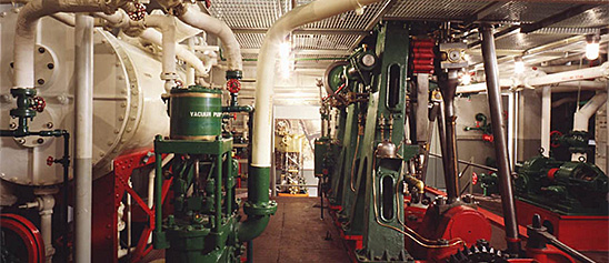
Engineering, Building, and Architecture

Not many museums collect houses. The National Museum of American History has four, as well as two outbuildings, 11 rooms, an elevator, many building components, and some architectural elements from the White House. Drafting manuals are supplemented by many prints of buildings and other architectural subjects. The breadth of the museum's collections adds some surprising objects to these holdings, such as fans, purses, handkerchiefs, T-shirts, and other objects bearing images of buildings.

The engineering artifacts document the history of civil and mechanical engineering in the United States. So far, the Museum has declined to collect dams, skyscrapers, and bridges, but these and other important engineering achievements are preserved through blueprints, drawings, models, photographs, sketches, paintings, technical reports, and field notes.

Crosby Steam Gauge & Valve Co. of Boston, Massachusetts, manufactured this steam engine indicator, serial number 330.
Description
Crosby Steam Gauge & Valve Co. of Boston, Massachusetts, manufactured this steam engine indicator, serial number 330. It consists of a brass piston with one groove, a vented brass cylinder, an internal, double wound spring which can be changed, and a small drum with a spiral spring and single record. The stylus is missing. Accompanying the indicator is a box with two springs, two turn cocks, a scale, and small tools.
This indicator was made for W. J. Hammer, Chief Inspector of Edison Light Co. There is a nickel-plated name plate on the front marked: “Property of W. J. Hammer, 65 Fifth Ave, New York.”
An engine indicator is an instrument for graphically recording the pressure versus piston displacement through an engine stroke cycle. Engineers use the resulting diagram to check the design and performance of the engine.
A mechanical indicator consists of a piston, spring, stylus, and recording system. The gas pressure of the cylinder deflects the piston and pushes against the spring, creating a linear relationship between the gas pressure and the deflection of the piston against the spring. The deflection is recorded by the stylus on a rotating drum that is connected to the piston. Most indicators incorporate a mechanical linkage to amplify the movement of the piston to increase the scale of the record.
When the ratio of the frequency of the pressure variation to the natural frequency of the system is small, then the dynamic deflection is equal to the static deflection. To design a system with a high natural frequency, the mass of the piston, spring, stylus, and mechanical linkage must be small, but the stiffness of the spring must be high. The indicator is subjected to high temperatures and pressures and rapid oscillations, imposing a limitation on the reduction in mass. Too stiff a spring will result in a small displacement of the indicator piston and a record too small to measure with accuracy. Multiplication of the displacement will introduce mechanical ad dynamic errors.
The parameters of the problem for designing an accurate and trouble free recorder are such that there is no easy or simple solution. Studying the variety of indicators in the collection shows how different inventors made different compromises in their designs.
Location
Currently not on view
date made
ca 1885
maker
Crosby Steam Gage & Valve Company
ID Number
MC.320555
catalog number
320555
accession number
241402
This notebook has a purple plastic cover, nylon spiral binding and is comprised of perforated index cards. The remaining cards are blank. It is easy to make a list or write down a task and tear it out.
Description
This notebook has a purple plastic cover, nylon spiral binding and is comprised of perforated index cards. The remaining cards are blank. It is easy to make a list or write down a task and tear it out. It was used by Jillian Gross while working for Habitat for Humanity, a not-for-profit, non-government organization advocating affordable housing around the world. It
When Hurricane Katrina struck the Gulf Coast in August 2005, Jillian Gross had worked with Habitat for Humanity for three years learning woodworking and house-building skills. Groups such as Habitat for Humanity marshaled volunteers, tools and lumber to step in when it became clear that normal avenues of housing assistance were overwhelmed.
In November 2005, Habitat for Humanity launched “America Builds on the National Mall,” a demonstration house-building marathon in Washington, D.C. in which the basic components of 51 homes were assembled within a week and shipped to the Gulf Coast. Upon completion of the project Ms. Gross, one of the house building leaders during this event, donated her tool belt, tools and protective wear to the Smithsonian Institution. The notebook was kept in the pocket of a tool belt.
Location
Currently not on view
ID Number
2005.0276.26
catalog number
2005.0276.26
accession number
2005.0276
This model was submitted to the U.S. Patent Office with the application for the patent issued to Andrew J. Peavey of Boston, Massachusetts, August 16, 1870, no.
Description
This model was submitted to the U.S. Patent Office with the application for the patent issued to Andrew J. Peavey of Boston, Massachusetts, August 16, 1870, no. 106400.
The model represents a stationary cylinder filled with oil within which turns a paddle wheel driven by the engine at a speed dependent upon the velocity of the engine. Also within the stationary cylinder and surrounding the paddle wheel is a hollow cylinder, which is hung loosely upon the shaft of the paddle wheel and is free to revolve independently of it. This cylinder has a series of blades or abutments projecting from the inner side of its rim, so that as the paddle wheel causes the oil to revolve in the cylinder the moving oil will come into contact with the abutments and tend to turn the loose cylinder. Attached to the loose cylinder is a pinion that meshes with a toothed sector, which, in turn, is connected with the counterweight and so tends to oppose the turning of that cylinder. As the height to which the counterweight will be raised is a function of the velocity of the engine, this velocity can be governed by properly connecting the counterweight to the cut-off or throttle valve.
Reference:
This description comes from the 1939 Catalog of the Mechanical Collections of the Division of Engineering United States Museum Bulletin 173 by Frank A. Taylor.
Location
Currently not on view
date made
1870
patent date
1870-08-16
inventor
Peavey, Andrew J.
ID Number
ER.308678
accession number
89797
catalog number
308678
patent number
106,400
This model was submitted to the U.S. Patent Office with the application for the patents issued to George H. Corliss, Providence, Rhode Island, August 26, 1862, nos.
Description
This model was submitted to the U.S. Patent Office with the application for the patents issued to George H. Corliss, Providence, Rhode Island, August 26, 1862, nos. 36279 and 36281.
The model represents a pair of internally fired, fire-tube boilers of the “locomotive” type, each equipped with a steam main connected to the steam space at six different points for the purpose of diffusing the draft of steam from over the whole surface of the water in the boiler and thus prevent priming; and provided with a salt-water evaporator located in the breeching, so as to obtain heat from the hot flue gases, and connected to the surface condenser to lower the pressure on the boiling salt water to facilitate evaporation.
The purpose of the peculiar arrangement of steam pipes is to provide a method of obtaining steam free from water without the necessity of a high steam chamber, which would be a vulnerable part of a naval vessel. The theory is that the filling of any of the many tubes with water, due to the pitching of the vessel, would cause the other tubes to supply the steam to the engines and the water would not travel far in the immersed tubes.
Reference:
This description comes from the 1939 Catalog of the Mechanical Collections of the Division of Engineering United States Museum Bulletin 173 by Frank A. Taylor.
Location
Currently not on view
date made
1862
patent date
1862-08-26
inventor
Corliss, George H.
ID Number
MC.308666
catalog number
308666
accession number
89797
patent number
36,279
36,281
This drill press was manufactured by Wilhelm Schröder GmbH & Company (Wilesco) of Lüdenscheid, Germany during the 20th century. The drill press is a Wilesco model M51.
Description (Brief)
This drill press was manufactured by Wilhelm Schröder GmbH & Company (Wilesco) of Lüdenscheid, Germany during the 20th century. The drill press is a Wilesco model M51. The press could be connected to the drive wheel of a toy steam engine for power and operate just like its full size counterpart.
Location
Currently not on view
date made
mid 20th century
ID Number
MC.329063
catalog number
329063
accession number
278175
This steel indicator, serial number S-37393, has a steel piston with a tapered cantilever socket. A small brass stylus can record a single cycle on paper wrapped around a small brass drum which is driven by string over a pulley.
Description
This steel indicator, serial number S-37393, has a steel piston with a tapered cantilever socket. A small brass stylus can record a single cycle on paper wrapped around a small brass drum which is driven by string over a pulley. Accompanying the indicator is a box with three additional tapered cantilevers, two pads of paper, four scales, three wrenches, and a box of tiny parts.
An engine indicator is an instrument for graphically recording the pressure versus piston displacement through an engine stroke cycle. Engineers use the resulting diagram to check the design and performance of the engine.
A mechanical indicator consists of a piston, spring, stylus, and recording system. The gas pressure of the cylinder deflects the piston and pushes against the spring, creating a linear relationship between the gas pressure and the deflection of the piston against the spring. The deflection is recorded by the stylus on a rotating drum that is connected to the piston. Most indicators incorporate a mechanical linkage to amplify the movement of the piston to increase the scale of the record.
When the ratio of the frequency of the pressure variation to the natural frequency of the system is small, then the dynamic deflection is equal to the static deflection. To design a system with a high natural frequency, the mass of the piston, spring, stylus, and mechanical linkage must be small, but the stiffness of the spring must be high. The indicator is subjected to high temperatures and pressures and rapid oscillations, imposing a limitation on the reduction in mass. Too stiff a spring will result in a small displacement of the indicator piston and a record too small to measure with accuracy. Multiplication of the displacement will introduce mechanical ad dynamic errors.
The parameters of the problem for designing an accurate and trouble free recorder are such that there is no easy or simple solution. Studying the variety of indicators in the collection shows how different inventors made different compromises in their designs.
Location
Currently not on view
ID Number
1981.0217.10
accession number
1981.0217
catalog number
1981.0217.10
The model was submitted to the U.S. Patent Office with the application for the patent issued to William S. Colwell, of Pittsburgh, Pennsylvania, September 16, 1879, no.
Description
The model was submitted to the U.S. Patent Office with the application for the patent issued to William S. Colwell, of Pittsburgh, Pennsylvania, September 16, 1879, no. 219622.
The model represents a reciprocating engine of more or less conventional steam engine design in which the operating fluid is vaporized carbon disulphide supplied by a boiler or generator and condensed in an air-cooled condenser. The transfer of heat from the fire in the boiler to the carbon disulphide and from the exhaust vapor to the cooling air of the condenser is effected through water. Plumbago, or black lead, is used to protect the walls of the generator and the engine from the action of the carbon-disulphide vapor. Steam and hot water from the water jacket of the generator are led into passages surrounding the engine cylinder and connecting pipes to prevent the loss of heat form the vapor.
Reference:
This description comes from the 1939 Catalog of the Mechanical Collections of the Division of Engineering United States Museum Bulletin 173 by Frank A. Taylor.
Location
Currently not on view
date made
1879
patent date
1879-09-16
inventor
Colwell, William S.
ID Number
MC.308766
catalog number
308766
accession number
89797
patent number
219,622
This is a 1/8-scale model of the tobacco ship Brilliant, a 250-ton vessel built in Virginia in 1775 for British owners.
Description
This is a 1/8-scale model of the tobacco ship Brilliant, a 250-ton vessel built in Virginia in 1775 for British owners. The Brilliant's first and probably only commercial venture from Virginia took place when it set sail for Liverpool, with a full hold of tobacco, in the summer of 1775. Typically the Brilliant would have returned with manufactured goods, but because of growing hostilities between Britain and the colonies, the ship remained in England. Records show that the Brilliant made one voyage to Jamaica and returned to London in 1776. Later that year, the Royal Navy purchased the vessel for just over £3,000 and converted it to a ship of war for service in the American Revolution.
The ship Brilliant had three masts and square-rigged sails. Its lower deck was 89'-3" long, its breadth was 27'-1/2", and the depth of the hold was 12'-2". The ship was built of oak, pine, and cedar. When purchased for war service, the Royal Navy assessed its hull, masts, and yards at £2,143. The cordage, including halyards, sheets, tack, and anchor cables, were assessed at £340. Brilliant's sails, 27 in all, were valued at £143. Five anchors were assessed at £58, while a long boat with a sailing rig and oars was estimated to be worth £45. Other items aboard the Brilliant were inventoried, including block and tackle, metal fittings, iron-bound water casks, hour and minute glasses, compasses, hammocks, an iron fire hearth, and 10 tons of coal.
After its conversion in 1776 as a ship of war in the Royal Navy, the Brilliant was commissioned as the HMS Druid. Its first voyage westbound across the Atlantic was as an escort for a convoy to the West Indies. The vessel served as the Druid until 1779, after which it became the fire ship Blast. In 1783, it was sold out of the service for £940 and, for the next 15 years, the former Virginia tobacco ship served as a whaler in Greenland. The vessel was lost in the Arctic in 1798.
This model was built by Charles and N. David Newcomb of Bolingbroke Marine in Trappe, Md. The model makers began their work in March 1975, scaling every timber to size and making everything out of the same type of wood as the original. They devised miniature rope-making equipment to manufacture the 5,000 feet of rigging and anchor cable required in 20 different sizes. Women from the Newcomb family and the surrounding community made the rigging and sails.
The model makers left the starboard side of the vessel unplanked to reveal the timbering and joinery of the hull and to permit a view of the vessel’s living accommodations in the stern and cargo stowage, complete with tobacco hogsheads.
Date made
1978
ship built
1775
voyage to Jamaica
1776
became a ship of war in Royal Navy
1776
ship lost at sea
1798
maker
Newcomb, Charles J.
Newcomb, N. David
ID Number
TR.335672
catalog number
335672
accession number
1978.0403
This model was filed to the U.S. Patent Office with the application for the patent issued to G. E. Dow, of San Francisco, California, November 4, 1879, no.
Description
This model was filed to the U.S. Patent Office with the application for the patent issued to G. E. Dow, of San Francisco, California, November 4, 1879, no. 221220.
The model represents a form of valve gear for a direct-connected steam engine in which the main valve is partially operated by a system of cam-shaped levers actuated from the main piston rod and partially by a supplementary steam piston, the movement of which is controlled by valves connected to the same levers.
Reference:
This description comes from the 1939 Catalog of the Mechanical Collections of the Division of Engineering United States Museum Bulletin 173 by Frank A. Taylor.
Location
Currently not on view
date made
1879
patent date
1879-11-04
inventor
Dow, George E.
ID Number
ER.308703
accession number
89797
catalog number
308703
patent number
221,220
This injector was submitted to the U.S. Patent Office with the application for the patent issued to Horace B. Murdock, of Detroit, Michigan, November 11, 1890, no.
Description
This injector was submitted to the U.S. Patent Office with the application for the patent issued to Horace B. Murdock, of Detroit, Michigan, November 11, 1890, no. 440183; assigned to the American Injector Co.
This is a double injector having two force tubes arranged in parallel order and operated with a single actuating shaft. The overflow valves as well as the steam valves of the two sets of tubes are operated by the same shaft so that the steam valve of the first set opens in advance of the steam valve of the second set and the overflow valve of the first set closes in advance of the second set. The stems of all conical plug valves are extended outside of the injector shell and are provided with slotted ends by which they may be turned with a suitable tool to grind upon the valve seats.
Reference:
This description comes from the 1939 Catalog of the Mechanical Collections of the Division of Engineering United States Museum Bulletin 173 by Frank A. Taylor.
Location
Currently not on view
date made
1890
patent date
1890-11-11
inventor
Murdock, Horace B.
ID Number
MC.309186
catalog number
309186
accession number
89797
patent number
440,183
This pencil was grouped with a number of pencils found in the pocket of a tool belt used by Jillian Gross while working for Habitat for Humanity, a not-for-profit, non-government organization advocating affordable housing around the world.
Description
This pencil was grouped with a number of pencils found in the pocket of a tool belt used by Jillian Gross while working for Habitat for Humanity, a not-for-profit, non-government organization advocating affordable housing around the world. Carpenter pencils have an two wide flat sides to keep them from rolling. The graphite core is generally wide and flat, making it easy to mark course materials when using the flat side while using the thinner side for precision marks.
When Hurricane Katrina struck the Gulf Coast in August 2005, Jillian Gross had worked with Habitat for Humanity for three years learning woodworking and house-building skills. Groups such as Habitat for Humanity marshaled volunteers, tools and lumber to step in when it became clear that normal avenues of housing assistance were overwhelmed.
In November 2005, Habitat for Humanity launched “America Builds on the National Mall,” a demonstration house-building marathon in Washington, D.C. in which the basic components of 51 homes were assembled within a week and shipped to the Gulf Coast. Upon completion of the project Ms. Gross, one of the house building leaders during this event, donated her tool belt, tools and protective wear to the Smithsonian Institution.
Location
Currently not on view
ID Number
2005.0276.28
catalog number
2005.0276.28
accession number
2005.0276
This circular saw was manufactured by Wilhelm Schröder GmbH & Company (Wilesco) of Lüdenscheid, Germany during the 20th century. The circular saw is a Wilesco model M53.
Description (Brief)
This circular saw was manufactured by Wilhelm Schröder GmbH & Company (Wilesco) of Lüdenscheid, Germany during the 20th century. The circular saw is a Wilesco model M53. The saw could be connected to the drive wheel of a toy steam engine for power and operate just like its full size counterpart.
Location
Currently not on view
date made
mid 20th century
ID Number
MC.329065
catalog number
329065
accession number
278175
This metal steam engine model was made by Greville Bathe in 1913. The horizontal table engine has a vertical cylinder and flywheel.
Description (Brief)
This metal steam engine model was made by Greville Bathe in 1913. The horizontal table engine has a vertical cylinder and flywheel. The donor of this item, Greville Bathe, was a machinist and engine hobbyist who would fashion his own parts to create model engines.
Location
Currently not on view
date made
1913
ID Number
MC.329024
catalog number
329024
accession number
278175
This toy steam traction engine was manufactured by Bing Works of Nuremberg, Germany around 1918-1932.
Description (Brief)
This toy steam traction engine was manufactured by Bing Works of Nuremberg, Germany around 1918-1932. The traction engine consists of a firebox below a boiler with a horizontal slide valve engine attached to a flywheel that drives the tractor’s rear wheel.
The Gebrüder Bing (Bing Brothers) toy company was founded in Nuremburg, Germany by Adolf and Ignatz Bing in 1863 and operated until 1932. The company was renamed Bing Werke (Bing Works) in 1918 when Ignatz Bing died. While very successful from 1863 until 1912, World War I created an unfavorable export market for German products, and the hard post-war years created additional financial hardships. The harsh political climate in Germany forced the Jewish Bing family to flee to England in 1932, and Bing’s assets were acquired by rival toy company Bub in 1933.
Location
Currently not on view
ID Number
MC.335707
catalog number
335707
accession number
1977.0920
This toy steam traction engine was manufactured by Bing Works of Nuremberg, Germany around 1918-1932.
Description (Brief)
This toy steam traction engine was manufactured by Bing Works of Nuremberg, Germany around 1918-1932. The traction engine consists of a black firebox below a boiler with a horizontal slide valve engine attached to a flywheel that is chained to the tractor’s rear wheel.
The Gebrüder Bing (Bing Brothers) toy company was founded in Nuremburg, Germany by Adolf and Ignatz Bing in 1863 and operated until 1932. The company was renamed Bing Werke (Bing Works) in 1918 when Ignatz Bing died. While very successful from 1863 until 1912, World War I created an unfavorable export market for German products, and the hard post-war years caused additional financial hardships. The harsh political climate in Germany forced the Jewish Bing family to flee to England in 1932, and Bing’s assets were acquired by rival toy company Bub in 1933.
Location
Currently not on view
date made
early 20th century
ID Number
MC.328930
catalog number
328930
accession number
278175
This model was submitted to the U.S. Patent Office with the application for the patent issued to Nicolaus A. Otto, of Deutz, Germany, and Francis W. and William J. Crossley, of Manchester, England, October 23, 1877, no.
Description
This model was submitted to the U.S. Patent Office with the application for the patent issued to Nicolaus A. Otto, of Deutz, Germany, and Francis W. and William J. Crossley, of Manchester, England, October 23, 1877, no. 196473.
The gas engine described is designed to effect a gradual combustion of the charge by the use of a weak mixture in the cylinder. In order that the mixture would not ignite too slowly a strong or explosive mixture was introduced into a separate but connecting chamber and ignited in the conventional way. The flame issuing with some force from the chamber into the cylinder effected a sufficiently rapid ignition of the weak charge.
The inventors also describe a means of raining the pressure on the cavity of the slide valve carrying the burning ignition charge in a flame ignition engine, high enough to equal the compression pressure within the cylinder of the engine.
Reference:
This description comes from the 1939 Catalog of the Mechanical Collections of the Division of Engineering United States Museum Bulletin 173 by Frank A. Taylor.
Location
Currently not on view
date made
1877
patent date
1877-10-23
inventor
Otto, Nicolaus A.
Crossley, Francis W.
Crossley, William J.
ID Number
MC.308695
catalog number
308695
accession number
89797
patent number
196,473
This toy boring mill was manufactured by the Märklin Company around 1920. The toy has a cast metal body, but is missing the ribbed steel band that runs from the lower pulley to the upper pulley to spin the cutting tool.
Description (Brief)
This toy boring mill was manufactured by the Märklin Company around 1920. The toy has a cast metal body, but is missing the ribbed steel band that runs from the lower pulley to the upper pulley to spin the cutting tool. The toy boring mill could be connected to the drive wheel of a toy steam engine for power and produce realistic motion just like its full size counterpart.
The Märklin Company was established in 1859 in the town of Göppingen, Germany by tin smith Theodor Friedrich Wilhelm Märklin. Märklin began his business with the production of tin doll houses, but the company soon began producing a variety of tinplate and metal items, eventually specializing in toys such as this one.
Location
Currently not on view
date made
ca 1920
ID Number
MC.329073
catalog number
329073
accession number
278175
This small, 3-cylinder, radial, air engine was designed and made by Henry James Kimman (1862-1921), a pioneer inventor of small portable piton air drills. It is believed that the engine was built for a steering engine on a steam roller.
Description
This small, 3-cylinder, radial, air engine was designed and made by Henry James Kimman (1862-1921), a pioneer inventor of small portable piton air drills. It is believed that the engine was built for a steering engine on a steam roller. The experience gained in the construction of the engine directed his interest to the design of air drills, in which field he made valuable contributions.
Reference:
This description comes from the 1939 Catalog of the Mechanical Collections of the Division of Engineering United States Museum Bulletin 173 by Frank A. Taylor.
Location
Currently not on view
date made
1900
ID Number
MC.310189
catalog number
310189
accession number
112722
This model was part of the application to the U.S. Patent Office for the patent issued to Frederick E. Sickels, of New York, New York, May 20, 1842, no. 2631.The Sickels valve gear is generally considered to be the first successful and practical drop cut-off.
Description
This model was part of the application to the U.S. Patent Office for the patent issued to Frederick E. Sickels, of New York, New York, May 20, 1842, no. 2631.
The Sickels valve gear is generally considered to be the first successful and practical drop cut-off. It was widely used on the engines of the side-wheel steamboats up to the beginning of the 20th century and was the forerunner of the many subsequent designs of drop cut-off valve gears. This valve gear provides a means of rapidly cutting off the admission of steam to the cylinder of the engine at any point in the stroke of the piston. It accomplishes this by tripping or disengaging the valve from the valve gear and permitting it to drop to its seat under the impulse of a spring. A plunger operating in a water chamber gradually retards the falling valve and brings it to rest without shock.
The Sickels valve is of the conical or poppet type, working vertically with the valve stem directed upward. Motion is transmitted to the valve through a lift rod working up and down continuously parallel to the valve stem. Spring clips on the lift rod engage with the projections on the valve stem and lift and open the valve, until the clips come into contact with wedge-shaped blocks, which spread the clips and permit the valve to fall back to its closed position. The wedge-shaped disengaging block can be placed so as to cause the valve to disengage and close at any desired instant during the up or down movement of the lift rod. A spring bearing upon the top of the valve stem causes it to close rapidly, while a plunger or piston attached to the underside of the valve and working in a chamber of water retards the valve gradually and permits it to close without shock. The lift rod may be actuated by an eccentric or, as was more usually the case, by cam and follower of the “alligator” jaw or steamboat type of gear.
Reference:
This description comes from the 1939 Catalog of the Mechanical Collections of the Division of Engineering United States Museum Bulletin 173 by Frank A. Taylor.
Location
Currently not on view
date made
1842
patent date
1842-05-20
ID Number
MC.308650
catalog number
308650
accession number
89797
patent number
2,631
The Weeden Manufacturing Company of New Bedford, Massachusetts manufactured the Weeden model number 12 toy steam engine from 1890 until 1906. This toy steam engine features dual horizontal boilers and dual horizontal slide valve engines connected to a single flywheel.
Description (Brief)
The Weeden Manufacturing Company of New Bedford, Massachusetts manufactured the Weeden model number 12 toy steam engine from 1890 until 1906. This toy steam engine features dual horizontal boilers and dual horizontal slide valve engines connected to a single flywheel. The dual engines are offset so one engine is pushing the flywheel at each time. A simulated brickwork metal firebox surrounds the two boilers, and the metal housing around the flywheel is made to look like brickwork as well. The entire engine is mounted on a metal plate.
The Weeden Manufacturing Company was founded in New Bedford, Massachusetts by William M. Weeden in the early 1880s, originally producing a variety of tinplate household items. In 1884 it introduced the Weeden No. 1 Steam engine as “a new and great premium for boys” who were subscribers to the Youth’s Companion magazine. Weeden made over a hundred different models of toy steam engines until the company ceased operations in 1952.
Location
Currently not on view
date made
late 19th century
ID Number
MC.328958
catalog number
328958
accession number
278175
The assembly line revolutionized labor and production in early 20th-century America, and its innovations of prefabricated parts and streamlined processes were applied to shipbuilding in World War I.
Description
The assembly line revolutionized labor and production in early 20th-century America, and its innovations of prefabricated parts and streamlined processes were applied to shipbuilding in World War I. This tool was used by shipyard workers to align pre-punched holes in standardized hull plates before riveting them together with steam-powered hydraulic riveting guns. Riveting was an exhausting task, but essential for ensuring the overall strength of these mass-produced freighters.
Beginning in 1918, the U.S. federal government initiated many programs designed to boost morale among workers on the home front. A popular event at shipyards was a riveting competition. The first record was set at the Baltimore Dry Dock and Shipbuilding Company, where a riveting gang drove 658 rivets in eight hours. As reports of this spread across the country, other shipyards tried for their own records and newspapers began offering cash prizes. The record climbed to 2,919 rivets in nine hours, but the United States Shipping Board soon realized that these publicity stunts were wearing out the riveting gangs. The board halted the contests, but began publishing a ranking system of each shipyard’s daily riveting totals to continue the friendly (and productive) rivalries.
date made
1918
first riveting competitions
1918
hosted riveting competitions
Baltimore Dry Dock and Shipbuilding Company
regulated riveting gangs and competitions
United States Shipping Board
ID Number
TR.336914
catalog number
336914
accession number
1979.0413
The Weeden no. 102 electric generator was produced by the Weeden Manufacturing Company of New Bedford, Massachusetts from 1913 until 1918. This was an earlier version of the model No. 102, as evidenced by the wooden base plate attached to the cast iron base.
Description (Brief)
The Weeden no. 102 electric generator was produced by the Weeden Manufacturing Company of New Bedford, Massachusetts from 1913 until 1918. This was an earlier version of the model No. 102, as evidenced by the wooden base plate attached to the cast iron base. It is an electromagnetic generator, producing a direct electric current through the rotation of a wire coil in a magnetic field. The generator could be connected to the flywheel of a Weeden steam engine, rotating the center coil, turning mechanical power into electricity.
The Weeden Manufacturing Company was founded in New Bedford, Massachusetts by William M. Weeden in the early 1880s, originally producing a variety of tinplate household items. In 1884 it introduced the Weeden No. 1 Steam engine as “a new and great premium for boys” who were subscribers to the Youth’s Companion magazine. Weeden made over a hundred different models of toy steam engines until the company ceased operations in 1952.
Location
Currently not on view
date made
ca 1900
ID Number
MC.322914
catalog number
322914
accession number
220719
The Bathe Manufacturing Company of Philadelphia, Pennsylvania manufactured this toy outboard marine gas engine during the early 20th century. The engine has two opposing cylinders with a two-blade propeller.
Description (Brief)
The Bathe Manufacturing Company of Philadelphia, Pennsylvania manufactured this toy outboard marine gas engine during the early 20th century. The engine has two opposing cylinders with a two-blade propeller. The Bathe Manufacturing Company was owned by Greville Bathe, a machinist and engine hobbyist who donated this object to the museum.
Location
Currently not on view
date made
early 20th century
ID Number
MC.329046
catalog number
329046
accession number
278175
The Lippincott Steam Specialty and Supply Co. manufactured this steam engine indicator, serial number 1380.
Description
The Lippincott Steam Specialty and Supply Co. manufactured this steam engine indicator, serial number 1380. It consists of a steel piston with two grooves and a bottom guide; a brass cylinder; an internal spring, which is missing; a small drum with a spiral spring and single record. The stylus is missing, but assumed to be a lead pencil point. Accompanying the indicator is a box with four springs, and extra piston, a wrench, reduction pulleys, record cards, and scales.
An engine indicator is an instrument for graphically recording the pressure versus piston displacement through an engine stroke cycle. Engineers use the resulting diagram to check the design and performance of the engine.
A mechanical indicator consists of a piston, spring, stylus, and recording system. The gas pressure of the cylinder deflects the piston and pushes against the spring, creating a linear relationship between the gas pressure and the deflection of the piston against the spring. The deflection is recorded by the stylus on a rotating drum that is connected to the piston. Most indicators incorporate a mechanical linkage to amplify the movement of the piston to increase the scale of the record.
When the ratio of the frequency of the pressure variation to the natural frequency of the system is small, then the dynamic deflection is equal to the static deflection. To design a system with a high natural frequency, the mass of the piston, spring, stylus, and mechanical linkage must be small, but the stiffness of the spring must be high. The indicator is subjected to high temperatures and pressures and rapid oscillations, imposing a limitation on the reduction in mass. Too stiff a spring will result in a small displacement of the indicator piston and a record too small to measure with accuracy. Multiplication of the displacement will introduce mechanical ad dynamic errors.
The parameters of the problem for designing an accurate and trouble free recorder are such that there is no easy or simple solution. Studying the variety of indicators in the collection shows how different inventors made different compromises in their designs.
Location
Currently not on view
ID Number
MC.316800
catalog number
316800
accession number
228496
patent number
1380

Our collection database is a work in progress. We may update this record based on further research and review. Learn more about our approach to sharing our collection online.

If you would like to know how you can use content on this page, see the Smithsonian's Terms of Use. If you need to request an image for publication or other use, please visit Rights and Reproductions.