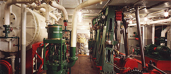
Engineering, Building, and Architecture

Not many museums collect houses. The National Museum of American History has four, as well as two outbuildings, 11 rooms, an elevator, many building components, and some architectural elements from the White House. Drafting manuals are supplemented by many prints of buildings and other architectural subjects. The breadth of the museum's collections adds some surprising objects to these holdings, such as fans, purses, handkerchiefs, T-shirts, and other objects bearing images of buildings.

The engineering artifacts document the history of civil and mechanical engineering in the United States. So far, the Museum has declined to collect dams, skyscrapers, and bridges, but these and other important engineering achievements are preserved through blueprints, drawings, models, photographs, sketches, paintings, technical reports, and field notes.

The Iron Fireman Manufacturing Company of Portland, Oregon produced this thermostat in the late 1930s. Iron Fireman began their company by producing coal furnaces that used an automatic coal-feeding system.
Description
The Iron Fireman Manufacturing Company of Portland, Oregon produced this thermostat in the late 1930s. Iron Fireman began their company by producing coal furnaces that used an automatic coal-feeding system. The thermostat could be set to a desired temperature and time, which would fire up the furnace and be automatically fed from a coal bin through a screw feed “ring drive” which delivered the coal to the bottom of the furnace. Delivering the coal below the furnace instead of dumping it on top generated more heat and used the coal more efficiently. This system allowed for coal to be used as an automatic fuel similar to gas or oil, keeping coal production economically viable in a time when it was losing market share to gas.
The ubiquity of thermostats in 21st century homes shrouds the decades of innovation, industrial design, and engineering that went into making them an everyday object in almost every home. In the early 20th century, a majority of American households still heated their homes with manually operated furnaces that required a trip down to the basement and stoking the coal fired furnace. Albert Butz’s “damper-flapper” system was patented in 1886 and allowed home owner to set the thermostat to a certain temperature which would open a damper to the furnace, increasing the fire and heating the house. Progressive innovations allowed for the thermostats to use gas lines, incorporate electricity, turn on at a set time, include heating and cooling in one mechanism, and even connect to the internet.
ID Number
2008.0011.02
accession number
2008.0011
catalog number
2008.0011.02
The Ernst Plank Company of Nuremberg, Germany manufactured this hot air engine around 1900. The engine is not a steam engine, as no water is heated. Instead the firebox heats air which expands and moves a piston to create useful mechanical work.
Description (Brief)
The Ernst Plank Company of Nuremberg, Germany manufactured this hot air engine around 1900. The engine is not a steam engine, as no water is heated. Instead the firebox heats air which expands and moves a piston to create useful mechanical work. The toy consists of a fire box to hear the air, with a piston powering a flywheel that is connected to a line shaft with three pulleys. The engine is very similar to the kind that ran the Praxinoscope toy made by Plank during the early 20th century.
Ernst Plank founded his company in Nuremburg, Germany in 1866. The company was well known for manufacturing a variety of metal toys like steam locomotives, stationary steam engines, early photography equipment, and magic lanterns until its dissolution in 1935.
Location
Currently not on view
date made
ca 1900
ID Number
MC.329055
catalog number
329055
accession number
278175
This walking beam engine model was manufactured by Stuart Models of Guernsey, Channel Islands, United Kingdom during the early 20th century. The model is a Watts “walking beam” that powers a flywheel.
Description (Brief)
This walking beam engine model was manufactured by Stuart Models of Guernsey, Channel Islands, United Kingdom during the early 20th century. The model is a Watts “walking beam” that powers a flywheel. The engine can run when hooked up to a power source such as a boiler or compressed air.
Location
Currently not on view
ID Number
MC.329029
catalog number
329029
accession number
278175
In the early nineteenth century, lighthouses in the United States were considered inferior to those in France and England.
Description
In the early nineteenth century, lighthouses in the United States were considered inferior to those in France and England. American mariners complained about the quality of the light emanating from local lighthouse towers, arguing that European lighthouses were more effective at shining bright beams of light over long distances. While American lighthouses relied on lamps and mirrors to direct mariners, European lighthouses were equipped with compact lenses that could shine for miles.
In 1822, French scientist Augustin-Jean Fresnel was studying optics and light waves. He discovered that by arranging a series of lenses and prisms into the shape of a beehive, the strength of lighthouse beams could be improved. His lens—known as the Fresnel lens—diffused light into beams that could be visible for miles. Fresnel designed his lenses in several different sizes, or orders. The first order lens, meant for use in coastal lighthouses, was the largest and the strongest lens. The sixth order lens was the smallest, designed for use in small harbors and ports.
By the 1860s, all of the lighthouses in the United States were fitted with Fresnel lenses. This lens came from a lighthouse on Bolivar Point, near Galveston, Texas. Galveston was the largest and busiest port in nineteenth-century Texas. Having a lighthouse here was imperative – the mouth of the bay provided entry to Houston and Texas City, as well as inland waterways. The Bolivar Point Light Station had second and third order Fresnel lenses over the years; this third order lens was installed in 1907. Its light could be seen from 17 miles away.
On 16-17 August 1915, a severe hurricane hit Galveston. As the storm grew worse, fifty to sixty people took refuge in the Bolivar Point Light Station. Around 9:15 PM, the light’s turning mechanism broke, forcing assistant lighthouse keeper J.B. Brooks to turn the Fresnel lens by hand. By 10 PM, the vibrations from the hurricane were so violent that Brooks began to worry the lens might shatter. He ceased turning the lens, trimmed the lamp wicks and worked to maintain a steady light through the night. The next morning, Brooks left the lighthouse to find Bolivar Point nearly swept away by the water.
Bolivar Point Light Station used this Fresnel lens until 1933. It was donated to the Smithsonian Institution by the National Park Service.
date made
1822
late 1800s
all United States lighthouses outfitted with Fresnel lenses
1860s
lens used during a severe hurricane at Bolivar Point
1917-08-16 - 1917-08-17
donated to Smithsonian
1933
inventor
Fresnel, Augustin Jean
ID Number
TR.335567
catalog number
335567
accession number
1977.0626
The Fleischmann No.155/1 Toy Steam Roller was produced by the Fleischmann Company of Nuremberg, Germany around 1953-1955.
Description (Brief)
The Fleischmann No.155/1 Toy Steam Roller was produced by the Fleischmann Company of Nuremberg, Germany around 1953-1955. Nuremburg toy companies were located in the American-occupied zone of Germany after World War II, and made toys exclusively for American resale as a way to get foreign currency into the country. Many Nuremburg tin toys from this time bear either the stamp “Made in US Zone Germany” or “Made in Western Germany ” as this one does. This steam roller consists of a black firebox, tin boiler, red cab with black canopy, and flywheel banded to back wheel that supplied the roller with its motion.
Location
Currently not on view
date made
mid 20th century
ID Number
MC.328927
catalog number
328927
accession number
278175
The Weeden Manufacturing Company of New Bedford, Massachusetts produced the Weeden No. 7 toy steam engine from 1890 until 1907. The Weeden No. 7 is features a horizontal boiler over a simulated brickwork firebox.
Description (Brief)
The Weeden Manufacturing Company of New Bedford, Massachusetts produced the Weeden No. 7 toy steam engine from 1890 until 1907. The Weeden No. 7 is features a horizontal boiler over a simulated brickwork firebox. The firebox holds a distinctive burner that has a small spouted fuel container with a fuel line that runs down to two wick holders. The horizontal engine is attached to a flywheel.
The Weeden Manufacturing Company was founded in New Bedford, Massachusetts by William M. Weeden in the early 1880s, originally producing a variety of tinplate household items. In 1884 it introduced the Weeden No. 1 Steam engine as “a new and great premium for boys” who were subscribers to the Youth’s Companion magazine. Weeden made over a hundred different models of toy steam engines until the company ceased operations in 1952.
Location
Currently not on view
date made
late 19th century
ID Number
MC.328957
catalog number
328957
accession number
278175
This model was submitted to the U.S. Patent Office with the application for the patent issued to Friedrich W. Gilles, of Kalk, Germany, July 11, 1876, no.
Description
This model was submitted to the U.S. Patent Office with the application for the patent issued to Friedrich W. Gilles, of Kalk, Germany, July 11, 1876, no. 179782.
The engine represented by the model is a 1-cylinder vertical gas engine employing two pistons, a working piston (the lower one) and a loose piston (the upper one). The loose piston was intended to fly to the top of the cylinder where it would be caught and held, producing within the cylinder a reduced pressure, which would cause the work piston to return under the pressure of the atmosphere and thereby perform work on the return stroke as well as the explosion stroke. Provision was made to cushion the free piston at the top of its stroke for the purpose of quiet running. The combustion mixture was drawn in and ignited on the explosion stroke without compression.
Reference:
This description comes from the 1939 Catalog of the Mechanical Collections of the Division of Engineering United States Museum Bulletin 173 by Frank A. Taylor.
Location
Currently not on view
date made
1876
patent date
1876-07-11
inventor
Gilles, Friedrich W.
ID Number
MC.311183
catalog number
311183
accession number
89797
patent number
179,782
Lehmann & Michels manufactured this gas engine indicator in Germany. According to a card inside the box, this style of indicator was invented by Voelcker about 1928.
Description
Lehmann & Michels manufactured this gas engine indicator in Germany. According to a card inside the box, this style of indicator was invented by Voelcker about 1928. It consists of a steel piston with one groove, a vented brass cylinder; an external, double wound spring, which can be changed; a small aluminum drum and single record. There is an additional device to turn the drum by a steel handle that is driven from the crank or cam shaft. Accompanying the indicator is a box with tools, one spring, extra parts, a pad of paper, and product literature.
An engine indicator is an instrument for graphically recording the pressure versus piston displacement through an engine stroke cycle. Engineers use the resulting diagram to check the design and performance of the engine.
A mechanical indicator consists of a piston, spring, stylus, and recording system. The gas pressure of the cylinder deflects the piston and pushes against the spring, creating a linear relationship between the gas pressure and the deflection of the piston against the spring. The deflection is recorded by the stylus on a rotating drum that is connected to the piston. Most indicators incorporate a mechanical linkage to amplify the movement of the piston to increase the scale of the record.
When the ratio of the frequency of the pressure variation to the natural frequency of the system is small, then the dynamic deflection is equal to the static deflection. To design a system with a high natural frequency, the mass of the piston, spring, stylus, and mechanical linkage must be small, but the stiffness of the spring must be high. The indicator is subjected to high temperatures and pressures and rapid oscillations, imposing a limitation on the reduction in mass. Too stiff a spring will result in a small displacement of the indicator piston and a record too small to measure with accuracy. Multiplication of the displacement will introduce mechanical ad dynamic errors.
The parameters of the problem for designing an accurate and trouble free recorder are such that there is no easy or simple solution. Studying the variety of indicators in the collection shows how different inventors made different compromises in their designs.
Location
Currently not on view
ID Number
1981.0217.11
accession number
1981.0217
catalog number
1981.0217.11
The Weeden Manufacturing Company of New Bedford, Massachusetts manufactured the Weeden model number 14 from the 1890s until the 1940s. The toy consists of a brass boiler with safety valve, whistle, and chimney stack (that was not original to the engine).
Description (Brief)
The Weeden Manufacturing Company of New Bedford, Massachusetts manufactured the Weeden model number 14 from the 1890s until the 1940s. The toy consists of a brass boiler with safety valve, whistle, and chimney stack (that was not original to the engine). The horizontal slide valve engine has an ornamental flyball governor and powers an iron flywheel. The boiler and engine is attached to a six-legged cast iron frame that is painted green. The side of the boiler has bears the Weeden crest logo that reads “W MFG. CO.” While this item is similar to object MC*328959 and is the same model, this engine has concave boiler ends and green iron base, pointing to an earlier manufacturing date. The later stack replaced an early style lever safety valve and there is no sight glass.
The Weeden Manufacturing Company was founded in New Bedford, Massachusetts by William M. Weeden in the early 1880s, originally producing a variety of tinplate household items. In 1884 it introduced the Weeden No. 1 Steam engine as “a new and great premium for boys” who were subscribers to the Youth’s Companion magazine. Weeden made over a hundred different models of toy steam engines until the company ceased operations in 1952.
Location
Currently not on view
date made
early 20th century
ID Number
MC.328961
catalog number
328961
accession number
278175
This toy electric motor was made by the H-K Electric Toy Company of Indianapolis, Indiana around 1906. The patents on this object refer to an electric toy that recreates mechanical motion.
Description (Brief)
This toy electric motor was made by the H-K Electric Toy Company of Indianapolis, Indiana around 1906. The patents on this object refer to an electric toy that recreates mechanical motion. A dry cell battery could fit in the center of the toy, energizing the electromagnets on the side, contracting its three lever-arms. When this contraction happens, the shaft rotates, and the protruding part of the shaft comes into contact with the metal prong causing the circuit that powered the electromagnet to break. This releases the lever-arms, which rotates the shaft as they rise, re-engaging the electromagnets and continuing the cycle. The weighted flywheel and staggered strength of the levers helped ensure that the drive shaft continued to rotate. The drive shaft could be connected to a variety of factory toys and provide them with a sense of realistic motion like their full size counterparts.
Location
Currently not on view
date made
1906
ID Number
MC.329034
catalog number
329034
accession number
278175
This 25 foot retractable tape measure has a bright orange plastic body and belt clip. The bright orange body makes it easy to locate.
Description
This 25 foot retractable tape measure has a bright orange plastic body and belt clip. The bright orange body makes it easy to locate. It was used by Jillian Gross while working for Habitat for Humanity, a not-for-profit, non-government organization advocating affordable housing around the world.
When Hurricane Katrina struck the Gulf Coast in August 2005, Jillian Gross had worked with Habitat for Humanity for three years learning woodworking and house-building skills. Groups such as Habitat for Humanity marshaled volunteers, tools and lumber to step in when it became clear that normal avenues of housing assistance were overwhelmed.
In November 2005, Habitat for Humanity launched “America Builds on the National Mall,” a demonstration house-building marathon in Washington, D.C. in which the basic components of 51 homes were assembled within a week and shipped to the Gulf Coast. Upon completion of the project Ms. Gross, one of the house building leaders during this event, donated her tool belt, tools and protective wear to the Smithsonian Institution. The tape measure was kept in the pocket of a tool belt.
Location
Currently not on view
ID Number
2005.0276.24
catalog number
2005.0276.24
accession number
2005.0276
Thomas and Bushnell manufactured this steam engine indicator, serial number 482, based on a design by Joseph Bachelder, who received patent number 360644 on April 5, 1887. It consists of a brass piston, a brass cylinder, and a large drum with a coil spring and a single record.
Description
Thomas and Bushnell manufactured this steam engine indicator, serial number 482, based on a design by Joseph Bachelder, who received patent number 360644 on April 5, 1887. It consists of a brass piston, a brass cylinder, and a large drum with a coil spring and a single record. The cantilever spring is enclosed in the tube; an adjustable fulcrum renders one spring usable over a range of values. Two springs are included: one low pressure 10-25 (20-50 pounds) and one high pressure 30-90 (60-175 pounds).
An engine indicator is an instrument for graphically recording the pressure versus piston displacement through an engine stroke cycle. Engineers use the resulting diagram to check the design and performance of the engine.
A mechanical indicator consists of a piston, spring, stylus, and recording system. The gas pressure of the cylinder deflects the piston and pushes against the spring, creating a linear relationship between the gas pressure and the deflection of the piston against the spring. The deflection is recorded by the stylus on a rotating drum that is connected to the piston. Most indicators incorporate a mechanical linkage to amplify the movement of the piston to increase the scale of the record.
When the ratio of the frequency of the pressure variation to the natural frequency of the system is small, then the dynamic deflection is equal to the static deflection. To design a system with a high natural frequency, the mass of the piston, spring, stylus, and mechanical linkage must be small, but the stiffness of the spring must be high. The indicator is subjected to high temperatures and pressures and rapid oscillations, imposing a limitation on the reduction in mass. Too stiff a spring will result in a small displacement of the indicator piston and a record too small to measure with accuracy. Multiplication of the displacement will introduce mechanical ad dynamic errors.
The parameters of the problem for designing an accurate and trouble free recorder are such that there is no easy or simple solution. Studying the variety of indicators in the collection shows how different inventors made different compromises in their designs.
Location
Currently not on view
date made
1887
ID Number
MC.316789
catalog number
316789
accession number
228496
Askania Werk A. G. manufactured this low pressure air indicator. It has a battery operated continuous recorder. The record is made with a metal stylus on a red waxed paper one inch in width. A small device separate from the recorder is evidently the sensing element.
Description
Askania Werk A. G. manufactured this low pressure air indicator. It has a battery operated continuous recorder. The record is made with a metal stylus on a red waxed paper one inch in width. A small device separate from the recorder is evidently the sensing element. There is a simple mechanical multiplication of the movement. The accompanying box contains several rolls of the red wax record paper.
An engine indicator is an instrument for graphically recording the pressure versus piston displacement through an engine stroke cycle. Engineers use the resulting diagram to check the design and performance of the engine.
A mechanical indicator consists of a piston, spring, stylus, and recording system. The gas pressure of the cylinder deflects the piston and pushes against the spring, creating a linear relationship between the gas pressure and the deflection of the piston against the spring. The deflection is recorded by the stylus on a rotating drum that is connected to the piston. Most indicators incorporate a mechanical linkage to amplify the movement of the piston to increase the scale of the record.
When the ratio of the frequency of the pressure variation to the natural frequency of the system is small, then the dynamic deflection is equal to the static deflection. To design a system with a high natural frequency, the mass of the piston, spring, stylus, and mechanical linkage must be small, but the stiffness of the spring must be high. The indicator is subjected to high temperatures and pressures and rapid oscillations, imposing a limitation on the reduction in mass. Too stiff a spring will result in a small displacement of the indicator piston and a record too small to measure with accuracy. Multiplication of the displacement will introduce mechanical ad dynamic errors.
The parameters of the problem for designing an accurate and trouble free recorder are such that there is no easy or simple solution. Studying the variety of indicators in the collection shows how different inventors made different compromises in their designs.
Location
Currently not on view
ID Number
1981.0217.20
accession number
1981.0217
catalog number
1981.0217.20
This steam engine toy was manufactured by an unknown maker during the early 20th century. The toy consists of a horizontal boiler that powers an engine and flywheel.
Description (Brief)
This steam engine toy was manufactured by an unknown maker during the early 20th century. The toy consists of a horizontal boiler that powers an engine and flywheel. A string attaches the toy windmill to the drive shaft of the engine that allowed the windmill’s blades to turn.
Location
Currently not on view
ID Number
MC.329061
catalog number
329061
accession number
278175
This toy steam traction engine was manufactured by an unknown German maker during the early 20th century. The traction engine consists of a black firebox below a boiler painted orange.
Description (Brief)
This toy steam traction engine was manufactured by an unknown German maker during the early 20th century. The traction engine consists of a black firebox below a boiler painted orange. The steam powers a horizontal slide valve engine attached to a flywheel that is chained to the tractor’s rear wheel.
Live steam toys enjoyed a period of popularity from the 1880s until the 1930s. The miniature steam engines were marketed as both toys and instructive devices that mimicked full-scale steam-powered machines and allowed every boy and girl to be their own engineer. In toy steam engines, a heating source is introduced into the firebox below the boiler (early toys used lit wicks fueled by denatured alcohol, later toys used electricity) which heated the water to produce the steam pressure that ran the engine. A variety of accessories could be powered by the engine; attachments included windmills, pumps, grinders, and electric lights. This traction engine achieves motion by the same method.
Location
Currently not on view
date made
early 20th century
ID Number
MC.328932
catalog number
328932
accession number
278175
Shimadzu manufactured this gas engine indicator. It is a photographic recorder with a four sided mirror for shutter and a drive with pulley and belt to an external motor. A sensing element is enclosed, but no description is available.
Description
Shimadzu manufactured this gas engine indicator. It is a photographic recorder with a four sided mirror for shutter and a drive with pulley and belt to an external motor. A sensing element is enclosed, but no description is available. Accompanying the indicator is a box with a wrench, two film holders and two cans of Kodak exposed film, extra film holder and mirror assembly. Additionally, there are two tool steel parts with short, knife edges, which are probably parts of the sensing element.
An engine indicator is an instrument for graphically recording the pressure versus piston displacement through an engine stroke cycle. Engineers use the resulting diagram to check the design and performance of the engine.
A mechanical indicator consists of a piston, spring, stylus, and recording system. The gas pressure of the cylinder deflects the piston and pushes against the spring, creating a linear relationship between the gas pressure and the deflection of the piston against the spring. The deflection is recorded by the stylus on a rotating drum that is connected to the piston. Most indicators incorporate a mechanical linkage to amplify the movement of the piston to increase the scale of the record.
When the ratio of the frequency of the pressure variation to the natural frequency of the system is small, then the dynamic deflection is equal to the static deflection. To design a system with a high natural frequency, the mass of the piston, spring, stylus, and mechanical linkage must be small, but the stiffness of the spring must be high. The indicator is subjected to high temperatures and pressures and rapid oscillations, imposing a limitation on the reduction in mass. Too stiff a spring will result in a small displacement of the indicator piston and a record too small to measure with accuracy. Multiplication of the displacement will introduce mechanical ad dynamic errors.
The parameters of the problem for designing an accurate and trouble free recorder are such that there is no easy or simple solution. Studying the variety of indicators in the collection shows how different inventors made different compromises in their designs.
Location
Currently not on view
ID Number
1981.0217.18
accession number
1981.0217
catalog number
1981.0217.18
This patent model accompanied Abijah S. Hosley’s patent application for a caliper to measure ship models that received patent number 8,307 on August 19, 1851. Vessel construction in the nineteenth century started with wooden models.
Description
This patent model accompanied Abijah S. Hosley’s patent application for a caliper to measure ship models that received patent number 8,307 on August 19, 1851. Vessel construction in the nineteenth century started with wooden models. Built to disassemble into pieces, the carefully shaped models would be taken apart and measured, and the measurements would be used to create full-sized patterns for fabricating the vessel's components. If drawings were created at all, they too were based on measurements from models. Hosley claimed his caliper provided greater accuracy, greater speed, and greater ease of use than ordinary measuring devices.
The ebony and brass model is comprised of two wooden posts attached to form an L. A curved handle projects from the top of the main post. A measuring arm slides along the bottom, its ivory scale and brass straight- edge rest. A second, curved measuring arm, now missing, once slid perpendicular to the secondary post; its headstock is still attached to the threaded rod that once adjusted its position. The secondary post's ivory scale is also missing. Two thumb screws at one end of the device control the measuring arms.
Location
Currently not on view
date made
1851
patent date
1851-08-19
patentee
Hosley, Abijah S.
inventor
Hosley, Abijah S.
ID Number
TR.308544
catalog number
308544
accession number
89797
patent number
8,307
This model was submitted to the U.S. Patent Office with the application for the patent issued to William Johnston, of Washington, DC, November 4, 1879, no. 221318.The compressor represented by the model is in effect a bellows.
Description
This model was submitted to the U.S. Patent Office with the application for the patent issued to William Johnston, of Washington, DC, November 4, 1879, no. 221318.
The compressor represented by the model is in effect a bellows. It is constructed as a cylindrical casing mounted upon a stationary horizontal shaft about which it oscillates. Two diaphragms extend in radial planes from the inside and top of the casing to a bearing on the upper side of the shaft. The space between these diaphragms is wedge-shaped. The two spaces thus formed are valve spaces, inlet and outlet, respectively. Flap valves are let into the diaphragm connecting the valve spaces with the lower part of the casing interior. A third diaphragm, called a lug, is fixed to the underside of the shaft and extends downward to the cylinder casing.
In use the casing is filled with water to the level of the center of the shaft. When the case is rocked the water is held approximately stationary by the lug and the air between the surface of the water and the diaphragm on the down side is compressed while a partial vacuum is formed in the space between the surface of the water and the diaphragm on the up side. The compressed air escapes through the outlet valve and air is drawn into the up side through the inlet valve. As the casing is rocked back and forth it is in effect a double-acting bellows.
Reference:
This description comes from the 1939 Catalog of the Mechanical Collections of the Division of Engineering United States Museum Bulletin 173 by Frank A. Taylor.
Location
Currently not on view
date made
1879
patent date
1879-11-04
inventor
Johnston, William
ID Number
MC.308706
catalog number
308706
accession number
89797
patent number
221,318
This toy steam engine was manufactured by the Ernst Plank Company of Nuremburg, Germany during the early 20th century.
Description (Brief)
This toy steam engine was manufactured by the Ernst Plank Company of Nuremburg, Germany during the early 20th century. The toy consists of dual horizontal boilers driving dual vertical oscillating engines that are connected to a single shaft moving two flywheels.
Ernst Plank founded his company in Nuremburg, Germany in 1866. The company was well known for manufacturing a variety of metal toys like steam locomotives, stationary steam engines, early photography equipment, and magic lanterns until its dissolution in 1935.
Location
Currently not on view
date made
ca 1900
ID Number
MC.329010
catalog number
329010
accession number
278175
The Star Brass Mfg. Co. manufactured this steam engine indicator, serial number 485. It consists of a steel piston; a steel cylinder; an external spring, which is missing; a small drum with a spiral spring and a single record. The stylus is missing, but is likely a pencil point.
Description
The Star Brass Mfg. Co. manufactured this steam engine indicator, serial number 485. It consists of a steel piston; a steel cylinder; an external spring, which is missing; a small drum with a spiral spring and a single record. The stylus is missing, but is likely a pencil point. The accompanying box has five double wound springs.
An engine indicator is an instrument for graphically recording the pressure versus piston displacement through an engine stroke cycle. Engineers use the resulting diagram to check the design and performance of the engine.
A mechanical indicator consists of a piston, spring, stylus, and recording system. The gas pressure of the cylinder deflects the piston and pushes against the spring, creating a linear relationship between the gas pressure and the deflection of the piston against the spring. The deflection is recorded by the stylus on a rotating drum that is connected to the piston. Most indicators incorporate a mechanical linkage to amplify the movement of the piston to increase the scale of the record.
When the ratio of the frequency of the pressure variation to the natural frequency of the system is small, then the dynamic deflection is equal to the static deflection. To design a system with a high natural frequency, the mass of the piston, spring, stylus, and mechanical linkage must be small, but the stiffness of the spring must be high. The indicator is subjected to high temperatures and pressures and rapid oscillations, imposing a limitation on the reduction in mass. Too stiff a spring will result in a small displacement of the indicator piston and a record too small to measure with accuracy. Multiplication of the displacement will introduce mechanical ad dynamic errors.
The parameters of the problem for designing an accurate and trouble free recorder are such that there is no easy or simple solution. Studying the variety of indicators in the collection shows how different inventors made different compromises in their designs.
Location
Currently not on view
ID Number
MC.316802
catalog number
316802
accession number
228496
This toy beam engine was made by an unknown manufacturer during the early 20th century. The toy is driven by a spring in its tin base. The engine consists of a vertical valve and walking beam shafted to a flywheel.Currently not on view
Description (Brief)
This toy beam engine was made by an unknown manufacturer during the early 20th century. The toy is driven by a spring in its tin base. The engine consists of a vertical valve and walking beam shafted to a flywheel.
Location
Currently not on view
ID Number
MC.329042
catalog number
329042
accession number
278175
The Weeden Manufacturing Company of New Bedford, Massachusetts produced this Weeden No. 34 toy steam engine during the late 19th century until around 1940. This toy steam engine features a brass boiler with two star cutouts, and three circular cutouts through the middle.
Description (Brief)
The Weeden Manufacturing Company of New Bedford, Massachusetts produced this Weeden No. 34 toy steam engine during the late 19th century until around 1940. This toy steam engine features a brass boiler with two star cutouts, and three circular cutouts through the middle. The horizontal boiler, flywheel, and engine sit on an iron frame. The engine is on top of the boiler, making this an “overtype” engine.
The Weeden Manufacturing Company was founded in New Bedford, Massachusetts by William M. Weeden in the early 1880s, originally producing a variety of tinplate household items. In 1884 it introduced the Weeden No. 1 Steam engine as “a new and great premium for boys” who were subscribers to the Youth’s Companion magazine. Weeden made over a hundred different models of toy steam engines until the company ceased operations in 1952.
Location
Currently not on view
date made
early 20th century
ID Number
MC.328965
catalog number
328965
accession number
278175
This waterline model represents the ms Zuiderdam, a cruise ship owned and operated by Holland America Line. The Zuiderdam was built in Marghera, Italy, by Fincantieri, a firm specializing in modern cruise ships, and began service in 2002.
Description
This waterline model represents the ms Zuiderdam, a cruise ship owned and operated by Holland America Line. The Zuiderdam was built in Marghera, Italy, by Fincantieri, a firm specializing in modern cruise ships, and began service in 2002. The ship is the first in Holland America’s Vista-class series, the company’s new line of vessels featuring diesel-electric power plants for energy savings and an Azipod propulsion system for greater maneuverability. All Vista-class vessels are 81,769 gross tons and carry 1,848 passengers with a crew of 800. The Zuiderdam’s home port is Rotterdam.
Holland America Line designs its ships and markets its cruises for what the industry considers the premium markets. The Zuiderdam features Venetian-themed artwork and offers a variety of suites, staterooms, restaurants, lounges, and cafes, as well as recreational facilities including a theater, a golf simulator room, a casino, and a spa. Like other large cruise ship companies, Holland America caters largely to American customers. It runs vessels in all of the major cruise markets, including the Caribbean, Alaska, Asia, the South Pacific, Europe, and the Mediterranean.
date made
2000
owned and operated
Holland America Line
firm who built the ship
Fincantieri
ID Number
2007.0172.01
catalog number
2007.0172.01
accession number
2007.0172
This Multi-function hand tool is for light quick work. It is meant to fold up and can be carried in a small pouch or pocket.
Description
This Multi-function hand tool is for light quick work. It is meant to fold up and can be carried in a small pouch or pocket. This tool is comprised of knife blades, screw driver heads, an awl, a saw blade, scissors, file, cork screw, bottle opener, a combination needlenose plier, regular plier, wire cutter and wire stripper. It closes up into a butterfly configuration. It was used by Jillian Gross while working for Habitat for Humanity, a not-for-profit, non-government organization advocating affordable housing around the world.
When Hurricane Katrina struck the Gulf Coast in August 2005, Jillian Gross had worked with Habitat for Humanity for three years learning woodworking and house-building skills. Groups such as Habitat for Humanity marshaled volunteers, tools and lumber to step in when it became clear that normal avenues of housing assistance were overwhelmed.
In November 2005, Habitat for Humanity launched “America Builds on the National Mall,” a demonstration house-building marathon in Washington, D.C. in which the basic components of 51 homes were assembled within a week and shipped to the Gulf Coast. Upon completion of the project Ms. Gross, one of the house building leaders during this event, donated her tool belt, tools and protective wear to the Smithsonian Institution.
Location
Currently not on view
ID Number
2005.0276.15
catalog number
2005.0276.15
accession number
2005.0276

Our collection database is a work in progress. We may update this record based on further research and review. Learn more about our approach to sharing our collection online.

If you would like to know how you can use content on this page, see the Smithsonian's Terms of Use. If you need to request an image for publication or other use, please visit Rights and Reproductions.