Industry & Manufacturing

The Museum's collections document centuries of remarkable changes in products, manufacturing processes, and the role of industry in American life. In the bargain, they preserve artifacts of great ingenuity, intricacy, and sometimes beauty.

The carding and spinning machinery built by Samuel Slater about 1790 helped establish the New England textile industry. Nylon-manufacturing machinery in the collections helped remake the same industry more than a century later. Machine tools from the 1850s are joined by a machine that produces computer chips. Thousands of patent models document the creativity of American innovators over more than 200 years.

The collections reach far beyond tools and machines. Some 460 episodes of the television series Industry on Parade celebrate American industry in the 1950s. Numerous photographic collections are a reminder of the scale and even the glamour of American industry.

This model was submitted to the U.S. Patent Office with the application for the patent issued to Henry Collinson, Boston, Massachusetts, April 13, 1875, no.
Description
This model was submitted to the U.S. Patent Office with the application for the patent issued to Henry Collinson, Boston, Massachusetts, April 13, 1875, no. 161934.
The invention consists of a lid or cover with a true flat face arranged in such a manner that while being forced home against a flat seat it receives a sliding and rotating motion thereon.
The model represents an opening in a plate around which is formed a flat plane face, which forms a seat for the dish –shaped lid or cover. A curved bar of metal spans the opening over the cover and supports a threaded nut through which passes a T-handled screw by which the cover is forced against the seat. At the inner end of the screw is an eccentric head that fits in a recess in the center of the cover, so that turning the screw forces the cover against the seat and moves the center of the cover in a circle, while the friction causes the cover to rotate somewhat about its own center. The result is a combined sliding and rotating of the cover as it is forced against the seat.
Reference:
This description comes from the 1939 Catalog of the Mechanical Collections of the Division of Engineering United States Museum Bulletin 173 by Frank A. Taylor.
Location
Currently not on view
date made
1875
patent date
1875-04-13
inventor
Collinson, Henry
ID Number
ER.309219
accession number
89797
catalog number
309219
patent number
161,934
Crosby Steam Gauge & Valve Co. of Boston, Massachusetts, manufactured this steam engine indicator, serial number 330.
Description
Crosby Steam Gauge & Valve Co. of Boston, Massachusetts, manufactured this steam engine indicator, serial number 330. It consists of a brass piston with one groove, a vented brass cylinder, an internal, double wound spring which can be changed, and a small drum with a spiral spring and single record. The stylus is missing. Accompanying the indicator is a box with two springs, two turn cocks, a scale, and small tools.
This indicator was made for W. J. Hammer, Chief Inspector of Edison Light Co. There is a nickel-plated name plate on the front marked: “Property of W. J. Hammer, 65 Fifth Ave, New York.”
An engine indicator is an instrument for graphically recording the pressure versus piston displacement through an engine stroke cycle. Engineers use the resulting diagram to check the design and performance of the engine.
A mechanical indicator consists of a piston, spring, stylus, and recording system. The gas pressure of the cylinder deflects the piston and pushes against the spring, creating a linear relationship between the gas pressure and the deflection of the piston against the spring. The deflection is recorded by the stylus on a rotating drum that is connected to the piston. Most indicators incorporate a mechanical linkage to amplify the movement of the piston to increase the scale of the record.
When the ratio of the frequency of the pressure variation to the natural frequency of the system is small, then the dynamic deflection is equal to the static deflection. To design a system with a high natural frequency, the mass of the piston, spring, stylus, and mechanical linkage must be small, but the stiffness of the spring must be high. The indicator is subjected to high temperatures and pressures and rapid oscillations, imposing a limitation on the reduction in mass. Too stiff a spring will result in a small displacement of the indicator piston and a record too small to measure with accuracy. Multiplication of the displacement will introduce mechanical ad dynamic errors.
The parameters of the problem for designing an accurate and trouble free recorder are such that there is no easy or simple solution. Studying the variety of indicators in the collection shows how different inventors made different compromises in their designs.
Location
Currently not on view
date made
ca 1885
maker
Crosby Steam Gage & Valve Company
ID Number
MC.320555
catalog number
320555
accession number
241402
This model was submitted to the U.S. Patent Office with the application for the patent issued to Andrew J. Peavey of Boston, Massachusetts, August 16, 1870, no.
Description
This model was submitted to the U.S. Patent Office with the application for the patent issued to Andrew J. Peavey of Boston, Massachusetts, August 16, 1870, no. 106400.
The model represents a stationary cylinder filled with oil within which turns a paddle wheel driven by the engine at a speed dependent upon the velocity of the engine. Also within the stationary cylinder and surrounding the paddle wheel is a hollow cylinder, which is hung loosely upon the shaft of the paddle wheel and is free to revolve independently of it. This cylinder has a series of blades or abutments projecting from the inner side of its rim, so that as the paddle wheel causes the oil to revolve in the cylinder the moving oil will come into contact with the abutments and tend to turn the loose cylinder. Attached to the loose cylinder is a pinion that meshes with a toothed sector, which, in turn, is connected with the counterweight and so tends to oppose the turning of that cylinder. As the height to which the counterweight will be raised is a function of the velocity of the engine, this velocity can be governed by properly connecting the counterweight to the cut-off or throttle valve.
Reference:
This description comes from the 1939 Catalog of the Mechanical Collections of the Division of Engineering United States Museum Bulletin 173 by Frank A. Taylor.
Location
Currently not on view
date made
1870
patent date
1870-08-16
inventor
Peavey, Andrew J.
ID Number
ER.308678
accession number
89797
catalog number
308678
patent number
106,400
This model was submitted to the U.S. Patent Office with the application for the patent issued to Joseph W. Fowle, of Boston, Massachusetts, August 14, 1877, no.
Description
This model was submitted to the U.S. Patent Office with the application for the patent issued to Joseph W. Fowle, of Boston, Massachusetts, August 14, 1877, no. 194037.
The model represents a 1-cylinder, vertical marine engine connected to a propeller shaft and propeller in the ordinary manner, with a float or inertia device for closing the throttle valve of the engine each time the vessel in which the engine is installed pitches sufficiently to raise the propeller out of the water.
The gear consists of a heavy weight suspended in suitable guides and stops near the keel of the ship. This weight is not rigidly fixed relative to the ship but tends to float in position as the vessel rises and falls. The change in relative positions actuates a valve lever on an auxiliary steam cylinder and piston, which, in turn, moves the main throttle valve of the engine.
Reference:
This description comes from the 1939 Catalog of the Mechanical Collections of the Division of Engineering United States Museum Bulletin 173 by Frank A. Taylor.
Location
Currently not on view
date made
1877
patent date
1877-08-14
inventor
Fowle, Joseph W.
ID Number
MC.308698
catalog number
308698
accession number
89797
patent number
194,037
Almost from the moment of the mechanical clock's invention, the local clock tower on a church or other public building dominated the landscape. Tower clocks announced the time to people within earshot of their bells and regulated urban life in the Western world.
Description
Almost from the moment of the mechanical clock's invention, the local clock tower on a church or other public building dominated the landscape. Tower clocks announced the time to people within earshot of their bells and regulated urban life in the Western world. The introduction of the pendulum and the anchor escapement in the late seventeenth century made these clocks remarkably accurate. They were set at local noon (when the sun reached its highest point in the sky at a particular location), and thus gave each town a time of its own, depending on its longitude.
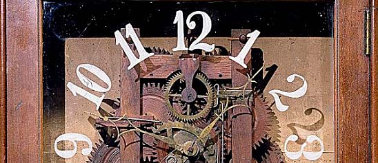
In America, before specialized manufacturers began mass-producing tower clocks in the second half of the nineteenth century, the clocks were built to order by versatile individual clockmakers and, occasionally, by adventurous blacksmiths. The tower clock shown here is one of the few built by Simon Willard (1753-1848) of Boston, the most famous of the many clockmaking members of the Willard family. Willard was inventive as well as prolific, a clockmaker who worked not only for a regional clientele but also for Thomas Jefferson and the outfitters of the U.S. Capitol.
Marked "Made in 1832 by Simon Willard in his 80th year," this tower clock served for more than a century on the First (Unitarian) Parish in Harvard Square in Cambridge, Massachusetts. In all details the movement shows uncompromising craftsmanship. It has a pinwheel dead-beat escapement with maintaining power and a rack-and-snail hour striking train.
Location
Currently not on view
Date made
1832
maker
Willard, Simon
ID Number
ME.330398
catalog number
330398
accession number
288890
Currently not on view
Location
Currently not on view
date made
1872
patent date
1872-04-02
inventor
Brayton, George B.
ID Number
MC.251280
catalog number
251280
accession number
48865
patent number
125,166
Samuel W. Lowe of Philadelphia invented the Lowe printing press, an unusual conical cylinder press patented in 1856. Like Adams's Cottage printing press, it did not include a frisket and included an automatic tympan.
Description
Samuel W. Lowe of Philadelphia invented the Lowe printing press, an unusual conical cylinder press patented in 1856. Like Adams's Cottage printing press, it did not include a frisket and included an automatic tympan. The rights for the press were sold in 1858 to Joseph Watson, who marketed both presses in Boston and Philadelphia.
The Lowe printing press does not appear to have been as heavily advertised as the Adams, although the company notes that we have sold many presses … to druggists … in this country and in other lands. Every boy and business man seems to be having one.
As for portability, the Lowe was more than a third lighter than the Adams, ranging from between 12 and 120 pounds as compared to Adams's press at between 100 and 400 pounds. The Lowe used a simpler frame and relatively thin castings.
date made
ca 1860
patent date
1856
maker
Lowe, Samuel W.
ID Number
1988.0650.03
accession number
1988.0650
catalog number
1988.0650.03
Sewing Machine Patent Model . Patent No. 6439, issued May 8, 1849John Bachelder of Boston, Massachusetts.John Bachelder of Boston, Massachusetts, submitted this sewing machine patent model for his Patent No. 6439, which was granted on May 8, 1849.
Description
Sewing Machine Patent Model . Patent No. 6439, issued May 8, 1849
John Bachelder of Boston, Massachusetts.
John Bachelder of Boston, Massachusetts, submitted this sewing machine patent model for his Patent No. 6439, which was granted on May 8, 1849. Bachelder’s machine sewed with a chain-stitch. He did not claim this chain-stitch mechanism as it was patented earlier in February in 1849 by Charles Morey and Joseph B. Johnson of Massachusetts. Instead he focused on improving the cloth feed. On this model, Bachelder used a wide continuous leather belt inserted with sharp pins to hold the cloth and enable the leather belt to move the cloth forward as it was being sewn. After being stitched, the fabric would be disengaged from the points by a curved piece of metal. This was the first patent for a continuous sewing, intermittent feeding mechanism.
Although Bachelder did not manufacture his sewing machine, his patent and later reissues of it were bought by I. M. Singer, and became one of the central patents to form the Sewing Machine Combination in 1856. This organization consisted of three sewing machine manufacturers, I. M. Singer Co., Wheeler & Wilson Co., and the Grover & Baker Co., and the inventor, Elias Howe Jr., who all agreed to pool their important patents and stop patent litigations between them. This allowed them to move ahead with manufacturing and marketing of their own sewing machine and collect license fees from other companies wanting to use their patents.
Location
Currently not on view
model constructed
before 1849-05-08
patent date
1849-05-08
inventor
Bachelder, John
ID Number
TE.T06051
catalog number
T06051.000
patent number
006439
accession number
89797
Five sizes of the Lowe printing press with kits were sold, with printing beds of between five by six inches and thirteen by seventeen inches. These dimensions reflect the range of sizes for completed printed documents.
Description
Five sizes of the Lowe printing press with kits were sold, with printing beds of between five by six inches and thirteen by seventeen inches. These dimensions reflect the range of sizes for completed printed documents.
date made
ca 1860
maker
Lowe, Samuel W.
manufacturer
Watson, Joseph
ID Number
2007.0162.013
accession number
2007.0162
catalog number
2007.0162.013
Gloucester fishermen working on the North Atlantic were exposed to harsh weather conditions. Waves and freezing rain splashed over the decks and into the dories while the men worked.
Description
Gloucester fishermen working on the North Atlantic were exposed to harsh weather conditions. Waves and freezing rain splashed over the decks and into the dories while the men worked. For some measure of protection, fishermen in the 19th century wore oiled clothes, the precursors to today’s waterproof foul weather gear.
This hat, referred to as a “Cape Ann sou’wester” because of its wide use in the fisheries around Cape Ann, Mass., is made of soft oiled canvas and lined with flannel. It has an elongated brim in the back to keep water from running down the wearer’s neck and inside his clothing. Ear flaps for warmth are also part of the hat’s design.
A catalog from the 1883 International Fisheries Exhibition in London claimed that with the sou’wester, “no class of seamen were so comfortably clothed as the New England fishermen.” At the time of the exhibition’s opening, sou’westers cost about $6.50 per dozen.
This Cape Ann sou’wester was displayed at the London exhibition, courtesy of its manufacturer, A. J. Tower of Boston, Mass. It was part of a display of the latest gear used and worn by American fishermen.
date made
early 1880s
used
late 19th century
on exhibit
1883
ID Number
2009.0157.03
catalog number
102126
accession number
2009.0157

Our collection database is a work in progress. We may update this record based on further research and review. Learn more about our approach to sharing our collection online.

If you would like to know how you can use content on this page, see the Smithsonian's Terms of Use. If you need to request an image for publication or other use, please visit Rights and Reproductions.