Measuring & Mapping

Where, how far, and how much? People have invented an astonishing array of devices to answer seemingly simple questions like these. Measuring and mapping objects in the Museum's collections include the instruments of the famous—Thomas Jefferson's thermometer and a pocket compass used by Meriwether Lewis and William Clark on their expedition across the American West. A timing device was part of the pioneering motion studies of Eadweard Muybridge in the late 1800s. Time measurement is represented in clocks from simple sundials to precise chronometers for mapping, surveying, and finding longitude. Everyday objects tell part of the story, too, from tape measures and electrical meters to more than 300 scales to measure food and drink. Maps of many kinds fill out the collections, from railroad surveys to star charts.

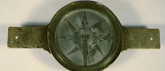
Surveyor's vernier compass marked "Wm. J. Young Maker Philadelphia." William J. Young began using this particular signature around 1840, and began putting serial numbers on his instruments in the early 1850s. The variation arc on the north arm extends 27 degrees either way.
Description
Surveyor's vernier compass marked "Wm. J. Young Maker Philadelphia." William J. Young began using this particular signature around 1840, and began putting serial numbers on his instruments in the early 1850s. The variation arc on the north arm extends 27 degrees either way. The vernier is moved by rack and pinion located on the south arm and hidden under a brass plate, and reads to 5 minutes. There is a circular level vial on the south arm and an outkeeper on the north arm. The face is dark, and the needle ring was probably silvered originally.
This compass belonged to David Newton Ellis (1850-1926), the County Surveyor of Monroe County, West Virginia.
Ref.: D. J. Warner, "William J. Young. From Craft to Industry in a Skilled Trade," Pennsylvania History 52 (1985): 53-68.
Location
Currently not on view
maker
Young, William J.
ID Number
1981.0648.02
accession number
1981.0648
catalog number
1981.0648.02
This solar compass, one of the earliest instruments of its kind, is marked "Burts patent Made by Wm. J. Young Philada." It belonged to Artemas Curtis, a brother–in–law of the inventor, William Austin Burt. It was made by William J.
Description
This solar compass, one of the earliest instruments of its kind, is marked "Burts patent Made by Wm. J. Young Philada." It belonged to Artemas Curtis, a brother–in–law of the inventor, William Austin Burt. It was made by William J. Young in Philadelphia, probably in 1840, and it nicely illustrates the complex process of developing a successful instrument. Following Burt's instructions, Young produced an instrument in which the vernier for the variation arc was moved by hand. When that design proved inconvenient, a tangent screw was added to move the vernier–and this tangent screw covered the signature. This example is of that type. In later examples, the signature appears where it can be easily read.
Ref: John S. Burt, They Left Their Mark. A Biography of William Austin Burt (Rancho Cordova, Ca., 1985).
Location
Currently not on view
maker
Young, William J.
inventor
Burt, William A.
ID Number
PH.328793
catalog number
328793
accession number
277834
This compass was made between 1853 and 1859. The "Jas. W. Queen, Philada. Warranted" inscription indicates that James W. Queen sold the compass and guaranteed its quality. The style, however, suggests that it was made by W. & L. E. Gurley, the Troy, N.
Description
This compass was made between 1853 and 1859. The "Jas. W. Queen, Philada. Warranted" inscription indicates that James W. Queen sold the compass and guaranteed its quality. The style, however, suggests that it was made by W. & L. E. Gurley, the Troy, N. Y., firm that was rapidly becoming the largest producer of complex mathematical instruments in the United States. The Queen Catalogue of 1859 offered several compasses, levels, and transits, with illustrations and descriptions copied from the Gurley Manual of 1855. A compass of this sort, with 6-inch needle, two straight levels, outkeeper, and mounting for use on a Jacob staff, cost $30. A paper label inside the box reads “James W. Queen 264 Chestnut St., near 10th, Philadelphia.”
Ref: James W. Queen & Co., Illustrated Catalogue of Mathematical, Optical, and Philosophical Instruments and School Apparatus (Philadelphia, 1859), p. 14.
Location
Currently not on view
date made
1853-1859
maker
W. & L. E. Gurley
ID Number
1982.0104.04
accession number
1982.0104
catalog number
1982.0104.04
An engine indicator is an instrument for graphically recording the pressure versus piston displacement through an engine stroke cycle. Engineers use the resulting diagram to check the design and performance of the engine. This indicator was designed and patented by C.B.
Description
An engine indicator is an instrument for graphically recording the pressure versus piston displacement through an engine stroke cycle. Engineers use the resulting diagram to check the design and performance of the engine. This indicator was designed and patented by C.B. Richards of Hartford, CT in 1863. Units of this design were manufactured by the American Steam Gauge Co. of Boston, MA and the Elliott Brothers of London, England.
Made of brass, it consists of a cylinder and piston and a separate drum mounted on a parallel axis holding the recording paper. The piston causes the stylus to rise and fall with pressure changes in the engine under measurement thereby directly recording the indicator’s output on the paper. Around the drum’s base is wound a cord that is attached to the connecting rod of the piston on the steam engine being measured. This causes the drum to rotate as the engine’s piston moves. An internal coil spring causes the cord to retract and the drum to counterrotate back to its original position as the connecting rod returns. The result is a steam pressure-volume diagram which is used to measure the efficiency and other attributes of the steam engine.
The Richards Indicator was a significant improvement over the then standard McNaught Indicator which was not fully satisfactory for measurements of high-speed steam engines. Richards' patent for his indicator makes note of the lightness and short stroke of the indicator's piston. This reduced the inertia of the moving parts of the unit and enabled its use on high speed engines. Richards’ patent also added the system of levers to the recording stylus in order to multiply the piston range by a factor of four while still producing a straight vertical motion proportional to the piston extension. This enabled a large and legible diagram to be traced on the drum even with the reduced piston range. The levers and pencil are made from lightweight materials to again reduce inertia.
The introduction of the steam indicator in the late 1790s and early 1800s by James Watt and others had a great impact on the understanding of how the steam behaved inside the engine's cylinder and thereby enabled much more exacting and sophisticated designs. The devices also changed how the economics and efficiency of steam engines were portrayed and marketed. They helped the prospective owner of a machine better understand how much his fuel costs would be for a given amount of work performed.
Measurement of fuel consumed and work delivered by the engine was begun by Watt, who in part justified the selling price of his engines on the amount of fuel cost the purchaser might save compared to an alternate engine. In the early days of steam power, the method to compare engine performance was based on a concept termed the engine’s “duty”. It originally was calculated as the number of pounds of water raised one foot high per one bushel of coal consumed. The duty method was open to criticism due to its inability to take into consideration finer points of efficiency in real world applications of engines. Accurate determination of fuel used in relation to work performed has been fundamental to the design and improvement of all steam-driven prime movers ever since Watt’s time. And, the steam indicators’ key contribution was the accurate measurements of performance while the engine was actually doing the work it was designed to do. This Richards steam indicator represented over one hundred years of evolution and improvement of the devices. Its ability to make recordings on high speed steam engines was a significant improvement for many applications.
date made
ca 1863
ID Number
MC.307515
catalog number
307515
accession number
68187
The image on this lithographic stone was prepared to print an image in the publication "United States Exploring Expedition, During the Years 1838, 1839, 1840, 1841, 1842," Volume 10, "Geology - Atlas," 1849.
Description (Brief)
The image on this lithographic stone was prepared to print an image in the publication "United States Exploring Expedition, During the Years 1838, 1839, 1840, 1841, 1842," Volume 10, "Geology - Atlas," 1849. The image depicts "Australian Fossils, Plate 4." The images was prepared by the lithographic firm Sarony & Major after illustrations by James Dwight Dana.
Description
The firm of Sarony & Major of Philadelphia, working between 1846 and 1857, prepared this lithographic printing stone after a drawing by Expedition Mineralogist James Dwight Dana (1813–1895) depicting Australian fossils. The lithographic illustration was published as Plate 4 in U.S. Exploring Expedition Volume X, Geology, by James D. Dana, 1849.
Location
Currently not on view
Date made
1849
publisher
Wilkes, Charles
original artist
Dana, James Dwight
graphic artist
Sarony & Major
printer
Sherman, Conger
ID Number
1999.0145.458
accession number
1999.0145
catalog number
1999.0145.458
William Helffricht was born in Frankfurt in 1807, moved to Philadelphia in 1825, and became a citizen in 1830. By the early 1830s he was advertising as a "Mathematical, Optical, & Philosophical Instrument Maker At the old established stand of the late Wm.
Description
William Helffricht was born in Frankfurt in 1807, moved to Philadelphia in 1825, and became a citizen in 1830. By the early 1830s he was advertising as a "Mathematical, Optical, & Philosophical Instrument Maker At the old established stand of the late Wm. DAVENPORT, Sign of the Quadrant, No. 25, South Front Street." Helffricht remained at this address until 1848.
This compass is inscribed "Wm Helffricht, Maker Philadelphia." It has a variation arc on the north arm that extends 25 degrees either way. The vernier reads to 5 minutes, and is moved by a rack and pinion under the south arm. There are two level vials on the south arm. A card in the wooden box reads "Wm. Helffricht No. 25 South Street, Philadelphia."
The compass was owned by Daniel Dunklin (1790-1844), who was elected governor of Missouri in 1832. Dunklin resigned the governorship in 1836, when Andrew Jackson named him surveyor-general of Missouri, Illinois, and Arkansas. He probably bought the compass at this time, and used it to trace the boundary between Missouri and Arkansas, and to lay out numerous counties in these three states.
Ref: "Daniel Dunklin" in National Cyclopaedia of American Biography, vol. 12, p. 303.
Location
Currently not on view
maker
Helffricht, William
ID Number
2001.0161.01
accession number
2001.0161
catalog number
2001.0161.01
This instrument isinscribed "Young & Sons, Philadelphia 5867" and dates from around 1875. The mark on the telescope-"Patented July 28th 1874"-refers to the patent (#153,494) granted to J. W. Nystrom and Alfred Young.
Description
This instrument isinscribed "Young & Sons, Philadelphia 5867" and dates from around 1875. The mark on the telescope-"Patented July 28th 1874"-refers to the patent (#153,494) granted to J. W. Nystrom and Alfred Young. It describes a method of regulating the focus of a telescope by moving the erecting lenses back and forth while keeping the object glass and cross hairs at a fixed distance from one another.
Location
Currently not on view
maker
Young & Sons
ID Number
PH.328750A
accession number
1988.0553
catalog number
328750A
Wm. J. Young & Sons (fl. 1870-1881) used a simple transit instrument of this sort as their logo, placing it on their advertisements and on the front cover of their Manual and Price List of Engineering and Mathematical Instruments. The inscription on this example reads "Wm. J.
Description
Wm. J. Young & Sons (fl. 1870-1881) used a simple transit instrument of this sort as their logo, placing it on their advertisements and on the front cover of their Manual and Price List of Engineering and Mathematical Instruments. The inscription on this example reads "Wm. J. Young & Sons 4648 Philadelphia." The serial number dates from 1872. The horizontal circle is silvered, graduated into 30 minutes of arc, and read by opposite verniers. One vernier reads to single minutes, and the other reads to 1/100 of a degree.
Location
Currently not on view
date made
1872
maker
William J. Young and Sons
ID Number
1985.0800.01
accession number
1985.0800
catalog number
1985.0800.01
This compass, which was designed to measure horizontal and vertical angles on hilly ground or in mines, resembles the one that the American surveyor, Lucius Lyon, described in 1828. It also resembles the Hedley's dial, devised in 1850 by John Hedley, H. M.
Description
This compass, which was designed to measure horizontal and vertical angles on hilly ground or in mines, resembles the one that the American surveyor, Lucius Lyon, described in 1828. It also resembles the Hedley's dial, devised in 1850 by John Hedley, H. M. Inspector of Mines in England. This example consists of a gimbal mounted vernier compass, a vertical arc, a sighting telescope, and a hanging level. The variation arc and vernier mechanisms are located on the compass face, under glass and protected from harm. The vertical arc is solid, graduated to 30 minutes, and read by vernier to single minutes. The inscription reads "JAMES REED & CO. Pittsburg, Pa. No. 383."
James Reed (1792-1878) was listed in the Pittsburgh directories in 1847 as a watch maker and jeweller. He began trading as James Reed & Co. in 1850, and in 1852 advertised as "Manufacturers of theodolites, surveyors compasses, leveling & grading instruments, &c."
Ref: Lucius Lyon, "Observations on Surveying Instruments, and the means of remedying their imperfections," American Journal of Science 14 (1828): 268-275.
William Ford Stanley, Surveying and Levelling Instruments (London, 1901), pp. 311-319.
Location
Currently not on view
maker
James Reed & Co.
ID Number
1985.0798.01
accession number
1985.0798
catalog number
1985.0798.01
The inscriptions on the face of this aneroid barometer read “Compensated” and “James W. Queen & Co. / PHILADELPHIA.” The pressure scale around the circumference extends from 18 to 31 inches of mercury.
Description
The inscriptions on the face of this aneroid barometer read “Compensated” and “James W. Queen & Co. / PHILADELPHIA.” The pressure scale around the circumference extends from 18 to 31 inches of mercury. The altitude scale extends to 15,000 feet elevation and is read by vernier and microscope to single feet. The diameter is about 3.5 inches. Although this instrument was sold by Queen, it was was probably made in London, perhaps by Short & Mason. New, it would have sold for $60.
Ref.: James W. Queen & Co., Priced and Illustrated Catalogue of Meteorological Instruments (Philadelphia, 1882), p. 93.
Location
Currently not on view
date made
1859-1896
maker
James W. Queen & Co.
ID Number
1996.0163.01
accession number
1996.0163
catalog number
1996.0163.01
This wye level was made by Edmund Draper in Philadelphia, around 1870. The inscriptions read "E. Draper. Philad" and "294."Currently not on view
Description
This wye level was made by Edmund Draper in Philadelphia, around 1870. The inscriptions read "E. Draper. Philad" and "294."
Location
Currently not on view
maker
Draper, Edmund
ID Number
PH.337021
accession number
1977.1101
catalog number
337021
This engraved printing plate was prepared to print an image of "Ptilonopus Perousei" (now Many-colored Fruit Dove, Ptilinopus perousii Peale (S.
Description (Brief)
This engraved printing plate was prepared to print an image of "Ptilonopus Perousei" (now Many-colored Fruit Dove, Ptilinopus perousii Peale (S. polynesia)) for the publication "United States Exploring Expedition, During the Years 1838, 1839, 1840, 1841, 1842," Volume 8, Mammalogy and Ornithology, plate 33, in the edition Philadelphia : J. B. Lippincott & Co., 1858. The engraving was produced by Robert Hinshelwood after T. R. Peale.
Description
Robert Hinshelwood (1812–after 1875) of New York City engraved this copper printing plate after a drawing by Expedition Naturalist Titian Ramsey Peale. The image depicts the Ptilonopus Perousei (now Many-colored Fruit Dove, Ptilinopus perousii Peale [S. polynesia]). The engraved illustration was published as Plate 33 in Volume VIII, Mammalogy and Ornithology, by John Cassin, 1858.
Location
Currently not on view
Date made
1858
publisher
Wilkes, Charles
original artist
Peale, Titian Ramsay
graphic artist
Hinshelwood, Robert
printer
Sherman, Conger
author
Cassin, John
ID Number
1999.0145.413
catalog number
1999.0145.413
accession number
1999.0145
The form of this compass suggests that it was made in the late 18th century. The "DEAN PHILAD" inscription refers to William Dean who, in an advertisement of June 4, 1792, described himself as a "mathematical instrument maker" who had "commenced business" at No.
Description
The form of this compass suggests that it was made in the late 18th century. The "DEAN PHILAD" inscription refers to William Dean who, in an advertisement of June 4, 1792, described himself as a "mathematical instrument maker" who had "commenced business" at No. 43, South Front Street, Philadelphia, "directly opposite the post-office." In another advertisement, this one dated January 31, 1794, Dean announced that he made and sold "Surveying instruments of every description, Theodolets, Circumferentors on an improved plan, with a noneus, &c., Leveling instruments with or without telescopes, Sextants, Quadrants, Mariner’s Compasses, &c. and every article requisite for navigation, surveying, levelling, &c."
Ref: Charles Smart, The Makers of Surveying Instruments in America Since 1700 (Troy, N.Y., 1962), pp. 36-37.
Advertisements in Dunlap’s American Daily Advertiser for June 4, 1792, and January 31, 1794.
Location
Currently not on view
maker
Dean, William
ID Number
2003.0156.01
accession number
2003.0156
catalog number
2003.0156.01
An engine indicator is an instrument for graphically recording the cylinder pressure versus piston displacement through an engine stroke cycle. Engineers use the resulting diagram to check the design and performance of the engine.
Description
An engine indicator is an instrument for graphically recording the cylinder pressure versus piston displacement through an engine stroke cycle. Engineers use the resulting diagram to check the design and performance of the engine. This type of indicator was invented by John McNaught of Glasgow, Scotland ca 1825. This particular unit was manufactured by Novelty Iron Works of New York around 1842.
The McNaught indicator was a significant improvement over the original Watt indicator which made steam-pressure diagrams on a flat piece of recording paper. The piston of the engine under test moved the paper horizontally, and the indicator’s piston moved the paper vertically in proportion to the pressure in the cylinder. McNaught’s improvement was the introduction of an oscillating drum which held the recording paper. The indicator is made of brass and consists of a cylinder and piston with internal spring and the separate recording drum. The piston causes the stylus to rise and fall with pressure changes in the engine under measurement thereby directly recording the indicator’s output on the paper. Around the drum’s base is wound a cord that is attached to the connecting rod of the piston on the steam engine being measured. This causes the drum to rotate as the engine’s piston moves. An internal coil spring causes the cord to retract and the drum to counterrotate back to its original position as the connecting rod returns. The result is a steam pressure-volume diagram which is used to measure the efficiency and other attributes of the steam engine.
The introduction of the steam indicator in the late 1790s and early 1800s by James Watt and others had a great impact on the understanding of how the steam behaved inside the engine's cylinder and thereby enabled much more exacting and sophisticated designs. The devices also changed how the economics and efficiency of steam engines were portrayed and marketed. They helped the prospective owner of a machine better understand how much his fuel costs would be for a given amount of work performed.
Measurement of fuel consumed and work delivered by the engine was begun by Watt, who in part justified the selling price of his engines on the amount of fuel cost the purchaser might save compared to an alternate engine. In the early days of steam power, the method to compare engine performance was based on a concept termed the engine’s “duty”. It originally was calculated as the number of pounds of water raised one foot high per one bushel of coal consumed. The duty method was open to criticism due to its inability to take into consideration finer points of efficiency in real world applications of engines. Accurate determination of fuel used in relation to work performed has been fundamental to the design and improvement of all steam-driven prime movers ever since Watt’s time. And, the steam indicators’ key contribution was the accurate measurements of performance while the engine was actually doing the work it was designed to do.
date made
ca 1825 - 1830
ID Number
MC.307516
accession number
68187
catalog number
307516
Sextant with a double brass frame of the sort introduced by Edward Troughton in London in 1788. The silvered scale is graduated every 10 minutes from -5° to +155° and read by vernier with tangent screw and swinging magnifier to 10 seconds of arc.
Description
Sextant with a double brass frame of the sort introduced by Edward Troughton in London in 1788. The silvered scale is graduated every 10 minutes from -5° to +155° and read by vernier with tangent screw and swinging magnifier to 10 seconds of arc. The "Riggs Brothers, Philadelphia" inscription came into use in 1865, and refers to a firm that sold instruments of this sort to American customers.
Location
Currently not on view
ID Number
1989.0010.01
catalog number
1989.0010.01
accession number
1989.0010
Most nineteenth century American clocks were cheaply made for the mass market and domestic use.
Description
Most nineteenth century American clocks were cheaply made for the mass market and domestic use. But a few firms made finely finished precision clocks for applications where accuracy was vital: determining the time of scientific observations, for example, or regulating other clocks and watches. One such firm was E. Howard and Company of Boston, specialists in quality clocks, watches and scales since 1842.
This high-quality clock, made by the firm in 1874, distributed Philadelphia time for the Gold and Stock Telegraph Company in that city. Subscribers to the firm’s service of telegraphed gold prices and stock quotations could also receive a time service to set their clocks. Fitted to the mechanical movement of this Howard timepiece are assemblies that interrupt an electric telegraph circuit to indicate every half minute, full minute, five minutes and the hour.
Before 1883, towns across the nation set their own times by observing the position of the sun, so there were hundreds of local times. Instead of Eastern Standard Time, for example, there was Philadelphia Standard Time or Charleston Standard Time. Beginning in the 1850s, railroads operated on regional times, each set to an agreed-upon, arbitrary standard time. By the 1880s, there were about fifty such regional railroad times.
In November 1883, most North American railroads voluntarily agreed to adopt a standardized railway time based on zones, a system from which the time zones in use today originated.
Location
Currently not on view
date made
1874
associated date
1874
associated institution
Allegheny Observatory
Gold and Stock Telegraph Company
associated person
Bentley, Henry
manufacturer
E. Howard & Co.
ID Number
ME.333468.01
catalog number
333468.01
accession number
294351
This instrument is a specialized timekeeper for determining longitude at sea. It is serial no. 1 from a run of approximately 10,000 similar timekeepers made by Hamilton Watch Co, Lancaster, PA in 1942.World War II created a dire chronometer shortage for the United States.
Description
This instrument is a specialized timekeeper for determining longitude at sea. It is serial no. 1 from a run of approximately 10,000 similar timekeepers made by Hamilton Watch Co, Lancaster, PA in 1942.
World War II created a dire chronometer shortage for the United States. Before the war, most chronometers for American military and civilian customers were imported. Only a few American firms—including William Bond & Son of Boston and the New York establishments of John Bliss Inc. and T.S. and J. D. Negus—finished chronometers from parts imported from European makers. Chronometer making was a craft, with only a few hundred produced in any given year. When the war started in 1941, European suppliers of parts and finished instruments halted exports to the United States.
Anticipating the arrival of war, the U.S. Naval Observatory had asked American domestic watch manufacturers in 1939 for their participation in mass-producing chronometers. Domestic watch manufacturers Hamilton and Elgin agreed to undertake the design and production, but only Hamilton’s product met Navy accuracy requirements. Hamilton delivered two prototypes to the Navy on 27 February 1942, which passed with an error rate of 1.55 seconds per day. The firm went on during the war to mass-produce 8900 more chronometers for the Navy, 1500 for merchant shipping and 500 for the Army. Between 1942 and 1944, the price dropped from $625 to $390 per timekeeper.
Hamilton’s design for its Model 21 chronometer did not copy traditional European standards. Instead the design introduced key changes to improve accuracy. The modifications included changes to the escapement and the chronometer’s oscillating unit—the balance and hairspring assembly.
To find longitude at sea, a chronometer would be set to the time of a place of known longitude, like Greenwich, England, the prime meridian. That time, carried to a remote location, could be compared to local time. Because one hour of difference in time equals 15 degrees difference in longitude, the difference in time between the chronometer and local time would yield local longitude.
References:
1. Dick, Steven J. Sky and Ocean Joined: The U. S. Naval Observatory 1830-2000. Cambridge: Cambridge University Press, 2003.
2. Whitney, Marvin. The Ship’s Chronometer. Cincinnati: American Watchmakers Institute Press, 1985.
Location
Currently not on view
date made
1941
1956
maker
Hamilton
ID Number
ME.314825
catalog number
314825
accession number
210893
This compass marked "Wm. J. Young Maker Philadelphia" has two notable features. One is that the variation arc and vernier mechanism are located on the compass face, under glass and protected from harm. A similar design appears in the drawing accompanying William J.
Description
This compass marked "Wm. J. Young Maker Philadelphia" has two notable features. One is that the variation arc and vernier mechanism are located on the compass face, under glass and protected from harm. A similar design appears in the drawing accompanying William J. Young's 1830 patent application for an "Improved Surveying Compass." That instrument, however, had a full divided circle rather than a small variation arc. The other feature of this compass--a dark face and a silvered needle ring--was also described in Young's patent, and seems to be found on all Young compasses with a needle 5 inches or longer. The Journal of the Franklin Institute 10 (1832): 34, explained that this improvement of Young's "consists in colouring the surface of the compass plate green, or bronzing it, instead of silvering it in the usual way, thereby relieving the eye from the unpleasant and injurious effects of the white plate. A narrow silvered rim surrounds the bronzed surface, giving a distinct view of the needle point."
This compass dates from the late 1840s or early 1850s, after the expiration of Young's patent and before Young began placing serial numbers on his instruments. The variation arc extends 20 some degrees either way, and is graduated to 30 minutes. The vernier is moved by rack and pinion located on the south arm and hidden under a brass plate, and reads to single minutes. There is an outkeeper and a level vial (now missing) on the north arm.
Ref: D. J. Warner, "William J. Young. From Craft to Industry in a Skilled Trade," Pennsylvania History 52 (1985): 53-68.
Location
Currently not on view
maker
Young, William J.
ID Number
1982.0104.03
accession number
1982.0104
catalog number
1982.0104.03
This compass has a wooden bowl gimbal mounted in a wooden box. The paper card has an ornate American eagle with a ribband in its mouth reading "E PLURIBUS UNUM" at north. The inscriptions read "Wm Helffricht. Philadelphia" and "W. H. C.
Description
This compass has a wooden bowl gimbal mounted in a wooden box. The paper card has an ornate American eagle with a ribband in its mouth reading "E PLURIBUS UNUM" at north. The inscriptions read "Wm Helffricht. Philadelphia" and "W. H. C. RIGGS, Front near Dock St." This card was probably made for William Davenport. It was used by his successor, William Helffricht. The overlaid signature is that of W. H. C. Riggs, a clock and watch maker in Philadelphia whose firm became W. H. C. Riggs & Son in 1863. On the side of the box is a trade card of Riggs & Brother, who were in business from 1865 to 1901.
Location
Currently not on view
date made
19th century
maker
Riggs & Brother
ID Number
PH.330471
catalog number
330471
accession number
291268
This engraved printing plate was prepared to print an image showing four fish species in the never published Volume 21-22, Ichthyology, part of the series of publications the "United States Exploring Expedition, During the Years 1838, 1839, 1840, 1841, 1842." The plate images wer
Description (Brief)
This engraved printing plate was prepared to print an image showing four fish species in the never published Volume 21-22, Ichthyology, part of the series of publications the "United States Exploring Expedition, During the Years 1838, 1839, 1840, 1841, 1842." The plate images were engraved by W. H. Dougal after Joseph Drayton.
Description
William H. Dougal (1822–1895) of New York and Washington, D.C., (after 1844) engraved this copper printing plate depicting four species of fish documented by the U.S. Exploring Expedition. The illustrations were to be published in Volumes XXII and XXIII, Ichthyology, by Louis Agassiz. Dougal engraved 26 of the 28 plates for this volume which was never printed.
Location
Currently not on view
Date made
1849
1862
publisher
Wilkes, Charles
original artist
Drayton, Joseph
graphic artist
Dougal, William H.
author
Agassiz, Louis
ID Number
1999.0145.435
accession number
1999.0145
catalog number
1999.0145.435
William J. Young mentioned this instrument in a letter that he sent to the inventor, William A. Burt, on June 14, 1848: "On the 21st of April I sent to Mr. John Ferris of Pauline, Dutchess Co. N.Y. one Solar Compass." A Ferris descendant gave it to the Smithsonian.
Description
William J. Young mentioned this instrument in a letter that he sent to the inventor, William A. Burt, on June 14, 1848: "On the 21st of April I sent to Mr. John Ferris of Pauline, Dutchess Co. N.Y. one Solar Compass." A Ferris descendant gave it to the Smithsonian. The horizontal circle is silvered, graduated to 30 minutes, and read by opposite verniers. A telescope is mounted at one side of the compass, and a counterweight is mounted on the other. With the telescope is a vertical circle that is graduated to 30 minutes, and read by vernier to single minutes. The inscriptions read: "Burts Patent" and "Made by Wm. J. Young Philada."
A solar compass is a railroad compass with a solar attachment that allows surveyors to find north by reference to the sun rather than by reference to the magnetic needle. The form originated with William Austin Burt, a United States Deputy Surveyor who began surveying government lands in Michigan in 1833. In 1835, while working in an area of Wisconsin where there were large deposits of iron ore, Burt experienced great difficulty in using his standard vernier compass. By December he had roughed out his ideas for a solar compass, and asked William J. Young to make a model that he could submit to the Patent Office. Burt received a patent (#9428) the following year, and the Franklin Institute awarded him the Scott’s Medal for this "ingenious" instrument. But, as the solar compass was not yet serviceable, Burt went back to the drawing board. In 1840, confident that he had solved all the problems of his design, Burt asked Young to produce solar compasses. In 1850, the year that Burt’s patent expired, the General Land Office adopted the solar compass as a standard instrument for all major boundary lines in regions of magnetic disturbance, and demand rose accordingly. Claiming that he had never received even $300 "for his right in said invention," Burt petitioned Congress to renew his patent, but to no avail.
Burt’s solar apparatus has three arcs: one for setting the latitude of the land to be surveyed; one for setting the declination of the sun; and one for setting the hour of the day. In the latter half of the 19th century, several instrument makers offered solar attachments of this sort that could be used with transit instruments.
Ref: William A. Burt, Description of the Solar Compass (Detroit, 1844).
William A. Burt, A Key to the Solar Compass, and Surveyor’s Companion (Philadelphia, 1855).
John Burt, History of the Solar Compass Invented by Wm. A. Burt (Detroit, 1878).
Location
Currently not on view
maker
Young, William J.
inventor
Burt, William A.
ID Number
1983.0548.03a
accession number
1983.0548
catalog number
1983.0548.03
1983.0548.03a
This engraved printing plate was prepared to print an image of "Procellaria nivea" (now Pagodroma nivea - Snow Petrel) for the publication "United States Exploring Expedition, During the Years 1838, 1839, 1840, 1841, 1842," Volume 8, Mammalogy and Ornithology, plate 42, in the ed
Description (Brief)
This engraved printing plate was prepared to print an image of "Procellaria nivea" (now Pagodroma nivea - Snow Petrel) for the publication "United States Exploring Expedition, During the Years 1838, 1839, 1840, 1841, 1842," Volume 8, Mammalogy and Ornithology, plate 42, in the edition Philadelphia : J. B. Lippincott & Co., 1858. The engraving was produced by Rawdon, Wright, Hatch and Edson after T. R. Peale.
Description
The firm of Rawdon, Wright, Hatch and Edson (1830s–1850s) of New York City prepared this copper printing plate after a drawing by Expedition Naturalist Titian Ramsey Peale. It depicts the Procellaria nivea (now Pagodroma nivea or Snow Petrel). The engraved illustration was published as Plate 42 in Volume VIII, Mammalogy and Ornithology, by John Cassin, 1858.
Location
Currently not on view
Date made
1858
publisher
Wilkes, Charles
original artist
Peale, Titian Ramsay
graphic artist
Rawdon, Wright, Hatch and Edson
printer
Sherman, Conger
author
Cassin, John
maker
Peale, Titian Ramsay
ID Number
1999.0145.422
accession number
1999.0145
catalog number
1999.0145.422
The "RITTENHOUSE & EVANS" inscription on this compass refers to Benjamin Rittenhouse and his nephew, Benjamin Evans, who worked together in Worcester Township, Pennsylvania, around 1798-1801.
Description
The "RITTENHOUSE & EVANS" inscription on this compass refers to Benjamin Rittenhouse and his nephew, Benjamin Evans, who worked together in Worcester Township, Pennsylvania, around 1798-1801. A variation arc on the south arm extends 15 degrees either way; the "folded" vernier is moved by rack and pinion and reads to 5 minutes. John Johnson (1771-1841), the Surveyor-General of Vermont, used this compass in 1817-1820 while surveying the boundary between Maine and Canada. His notes refer to it as "a Circumferentor of 2.5 inches Radius made at Philadelphia by Rittenhouse and Evans and graduated to every 5 Minutes by the help of a nonius."
Ref: "John Johnson" in Abby M. Hemenway, ed., The Vermont Historical Gazeteer (Burlington, Vt., 1868), vol. 1, pp. 596-599
"John Johnson," in National Cyclopaedia of American History, vol. 17, pp. 290-291
Johnson's report on the Maine-Canada boundary survey, in University of Vermont Library.
Location
Currently not on view
user
Johnson, John
maker
Rittenhouse and Evans
ID Number
PH.309543
accession number
95588
catalog number
309543
This engraved printing plate was prepared to print an image of "Pleiodus strigirostris" (now Didunculus strigirostris - Tooth-billed Pigeon or Samoan Pigeon) for the publication "United States Exploring Expedition, During the Years 1838, 1839, 1840, 1841, 1842," Volume 8, Mammalo
Description (Brief)
This engraved printing plate was prepared to print an image of "Pleiodus strigirostris" (now Didunculus strigirostris - Tooth-billed Pigeon or Samoan Pigeon) for the publication "United States Exploring Expedition, During the Years 1838, 1839, 1840, 1841, 1842," Volume 8, Mammalogy and Ornithology, plate 34, in the edition Philadelphia : J. B. Lippincott & Co., 1858. The engraving was produced by W. H. Dougal after T. R. Peale.
Description
William H. Dougal (1822–1895) of New York and Washington, D.C., (after 1844) engraved this copper printing plate after a drawing by Expedition Naturalist Titian Ramsey Peale. The image depicts the Pleiodus strigirostris (now Didunculus strigirostris, Tooth billed pigeon or Samoan Pigeon). The engraved illustration was published as Plate 34 in Volume VIII, Mammalogy and Ornithology, by John Cassin, 1858.
Location
Currently not on view
Date made
1858
publisher
Wilkes, Charles
original artist
Peale, Titian Ramsay
graphic artist
Dougal, William H.
printer
Sherman, Conger
author
Cassin, John
ID Number
1999.0145.414
catalog number
1999.0145.414
accession number
1999.0145

Our collection database is a work in progress. We may update this record based on further research and review. Learn more about our approach to sharing our collection online.

If you would like to know how you can use content on this page, see the Smithsonian's Terms of Use. If you need to request an image for publication or other use, please visit Rights and Reproductions.