Measuring & Mapping

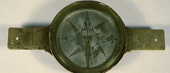
Where, how far, and how much? People have invented an astonishing array of devices to answer seemingly simple questions like these. Measuring and mapping objects in the Museum's collections include the instruments of the famous—Thomas Jefferson's thermometer and a pocket compass used by Meriwether Lewis and William Clark on their expedition across the American West. A timing device was part of the pioneering motion studies of Eadweard Muybridge in the late 1800s. Time measurement is represented in clocks from simple sundials to precise chronometers for mapping, surveying, and finding longitude. Everyday objects tell part of the story, too, from tape measures and electrical meters to more than 300 scales to measure food and drink. Maps of many kinds fill out the collections, from railroad surveys to star charts.

The U. S. Coast and Geodetic Survey Precise Level "is constructed without regard to cost, extreme accuracy being the governing consideration.
Description
The U. S. Coast and Geodetic Survey Precise Level "is constructed without regard to cost, extreme accuracy being the governing consideration. This fact accounts for the seemingly high price, which is for the complete instrument, with two achromatic eye–pieces, graduated and chambered level–vial having a value of 2 seconds per division. Completed packed, with extra heavy tripod...$300." Thus wrote G. N. Saegmuller, proprietor of Fauth & Co., describing the Precise Level that had been developed by E. G. Fischer and his colleagues in the Instrument Division of the Coast and Geodetic Survey. This example, marked "FAUTH & CO. WASHN. D.C. 2239" was made between 1900, when the form was introduced, and 1905, when Fauth went out of business. It belonged to the University of Missouri at Columbia.
To minimize changes due to temperature variation, Fischer's team developed an iron–nickel alloy with a very low coefficient of expansion. They also placed the telescope tube within a slightly larger tube, and sealed the openings between the tubes with chamois leather collars. To minimize disruptions caused by changes in weight or pressure upon the ground, Fischer's team mounted the level above the telescope. A mirror, mounted above the level, reflects an image of the bubble into a tube at the left side of the telescope. Thus, while the surveyor's right eye looks through the telescope to the distant rod, his/her left eye can see both ends of the level vial.
The Fischer level was Fauth's third precise level. The first was similar to the instrument that Kern had shown at the 1876 Centennial Exhibition held in Philadelphia. The second, unveiled in 1879, was based on a design originating in Vienna, Austria, and developed in the Instrument Shop of the Coast and Geodetic Survey, which was then under Saegmuller's direction.
Ref: E. G. Fischer, "Description of Precise Levels Nos. 7 and 8," Report of the Director of the United States Coast and Geodetic Survey (1900), Appendix 6.
George N. Saegmuller, Descriptive Price–List of First–Class Engineering & Astronomical Instruments (Washington, D.C., 1903), pp. 60–61.
Randall Brooks and Heather Bajdik, "Precise Levels in Surveys of North America," Rittenhouse 10 (1996): 48–57.
Location
Currently not on view
maker
Fauth & Co.
ID Number
PH.333634
catalog number
333634
accession number
300659
This transit marked "USC&GS No. 18" was designed by E. G. Fischer, chief mechanician of the U. S. Coast and Geodetic Survey. It is one of two identical instruments that were built in the Survey's instrument shop in 1888–1889.
Description
This transit marked "USC&GS No. 18" was designed by E. G. Fischer, chief mechanician of the U. S. Coast and Geodetic Survey. It is one of two identical instruments that were built in the Survey's instrument shop in 1888–1889. They were said to be "the most complete and best constructed transits the Survey has ever had for longitude." They had about the same optical power as the transits that Troughton & Simms had made in the 1840s, but weighed substantially less. When packed in two boxes for transportation, each instrument weighed "only" about 350 pounds. John Clacey made the objective lenses, and Edward Kahler made the eyepieces.
G. N. Saegmuller, who offered an apparently identical instrument for $900, termed it a "Coast Survey Transit. No. 30" and noted that the Survey used instruments of this sort "for time observations only."
Ref: Edwin Smith, "A Description of Two New Portable Transit Instruments for Longitude Work," Report of the Superintendent of the U.S. Coast and Geodetic Survey for 1889 (Washington, D.C., 1890), Appendix No. 9.
G. N. Saegmuller, Descriptive Price–List of First–Class Engineering & Astronomical Instruments (Washington, D.C., 1903), p. 75.
Location
Currently not on view
ID Number
PH.316661.01
accession number
226636
catalog number
316661
This theodolite magnetometer is based on the design that the U.S. Coast and Geodetic Survey developed in 1892-1893. It is similar in many ways to the instrument that the Survey had been using since the early 1880s, but with several new features.
Description
This theodolite magnetometer is based on the design that the U.S. Coast and Geodetic Survey developed in 1892-1893. It is similar in many ways to the instrument that the Survey had been using since the early 1880s, but with several new features. One is the octagonal shape of the collimating magnets. Another is the black velvet screen that connects the telescope with the suspension box: this cuts off stray light and eliminates the problems that had been caused by the glass window in the earlier form. It is marked "FAUTH & CO. WASHN D.C. 941" and "T.M.C.I. 1." The serial number suggests that it was made around 1895.
This instrument belonged to the Department of Terrestrial Magnetism of the Carnegie Institution of Washington. Internal records indicate that D.T.M. purchased it from Kolesch & Co. in New York in 1906 (for $175), sent it to Bausch, Lomb, Saegmuller Co. for repairs (another $120), and kept it in service until 1919.
Ref: Edwin Smith, "Notes on Some Instruments Recently Made in the Instrument Division of the Coast and Geodetic Survey Office," Annual Report of the Superintendent of the U.S. Coast and Geodetic Survey for 1894, Appendix No. 8.
Location
Currently not on view
Date made
ca 1895
maker
Fauth
Fauth & Co.
ID Number
1983.0039.04
accession number
1983.0039
catalog number
1983.0039.04
This instrument is marked "Geo. Shilling Washn D.C." and "U.S.G.S." It was made for the U.S. Geological Survey, and transferred to the Smithsonian in 1907. The horizontal circle and vertical arc are silvered, graduated to 30 minutes, and read by verniers to single minutes.
Description
This instrument is marked "Geo. Shilling Washn D.C." and "U.S.G.S." It was made for the U.S. Geological Survey, and transferred to the Smithsonian in 1907. The horizontal circle and vertical arc are silvered, graduated to 30 minutes, and read by verniers to single minutes. A level vial sits atop the telescope; another level vial sits on the horizontal circle. The inside of the lens cap is marked "U.S.G.S. No 2."
George Shilling (1844–1917) was born and educated in Norway and moved to the United States in 1867. In 1882, after working in several American instrument shops, he went into business on his own, manufacturing surveying and astronomical instruments. His shop was in Washington, D.C., and the federal government was his biggest customer.
Location
Currently not on view
maker
Shilling, George
ID Number
PH.247906
catalog number
247906
accession number
47736
There is no cartouche on this globe, but the texts on the horizon circle read: “IMPROVED GLOBE BOSTON” and “REFERENCES / Flamstead 46. Hevelius 24. Piazzi 180. LaCaille 1661. Nebulae. W. Herschell, J. Herschell, & J. Dunlop.” and “MANUFACTURED FOR H. B. NIMS & CO.
Description
There is no cartouche on this globe, but the texts on the horizon circle read: “IMPROVED GLOBE BOSTON” and “REFERENCES / Flamstead 46. Hevelius 24. Piazzi 180. LaCaille 1661. Nebulae. W. Herschell, J. Herschell, & J. Dunlop.” and “MANUFACTURED FOR H. B. NIMS & CO. / TROY N.Y.” and “THE EQUATION OF TIME” and “Entered according to Act of Congress, in the year 1852 by Charles Copley, in / the Clerks office, of the District Court, of the Southern District, of New York” and “MAGNITUDES / First Magnitude. . . Ninth Nebulae” and “EXPLANATION. / Ancient Constellations . . . Modern . . .”
This globe has a short 4-leg wooden base, a wooden horizon circle and a brass meridian. The astronomical information on the horizon circle suggests that this element could be used for celestial as well as terrestrial globes.
Charles Copley (b. 1800) was a cartographer and engraver from England who became an American citizen in 1844 and lived in Brooklyn. He is best known for the pair of 16-inch globes that he introduced in 1852. Despite being extremely detailed, even to the point of obscurity, these globes won a gold medal at the 1852 fair of the American Institute in New York, and a first premium at the 1853 fair of the Franklin Institute in Philadelphia. Copley’s globes would be revised from time to time, and marketed by other firms.
This example of Copley’s terrestrial globe contains revisions that would have been of particular interest to Americans: Alaska (1867) is shown, but Lake Victoria (1858) and Mt. Kilimanjaro (1848) are not. Other additions include isothermal lines, the Atlantic Cable, and various deep sea soundings which, as advertised, “are not laid down on any other globe.”
H. B. Nims & Co., the firm that marketed this example, was in business in Troy, N.Y., from 1869 to 1885 and again from 1890 to 1896, publishing and selling books and other school supplies. The globe was probably made by Gilman Joslin in Boston.
Ref: D. J. Warner, “The Geography of Heaven and Earth,” Rittenhouse 2 (1999): 54-55, 63-64, and 88-89.
Location
Currently not on view
date made
ca 1870
maker
Copley, Charles
Joslin, Gilman
H. B. Nims & Co.
ID Number
PH.327974
accession number
270024
catalog number
327974
William J. Peters of the U. S. Geological Survey devised this type of instrument in 1898, while doing reconnaissance work in Alaska. G. N.
Description
William J. Peters of the U. S. Geological Survey devised this type of instrument in 1898, while doing reconnaissance work in Alaska. G. N. Saegmuller, proprietor of Fauth & Co., explained its function: "Having a fixed base of known dimensions defined by targets, the measurement is made by bringing the images of the targets together by moving the halved objective by means of a micrometer screw." The Geological Survey transferred this example to the Smithsonian in 1907, reporting that "Distances up to 1 or 2 miles can be determined with sufficient accuracy for reconnaissance work."
This is actually a composite instrument. The prism monocular was probably made by Bausch & Lomb in Rochester, N.Y., according to the design developed by Zeiss in Jena, Germany, while Saegmuller made the divided object glass micrometer. It is notably different from the stenometer that Saegmuller was offering in 1901, and so is probably an early prototype. The words "U.S.G.S. No. 4" are scratched onto its surface.
Ref: George N. Saegmuller, Descriptive Price-List of First-Class Engineering & Astronomical Instruments (Washington, D.C., 1901), p. 108.
Location
Currently not on view
maker
Fauth & Co.
ID Number
PH.247921
catalog number
247921
accession number
47736
Thomas Sinclair (ca 1805-1881) of Philadelphia produced this chromolithographic print of "Chrysomitris marginalis [Bonaparte] male and female" (common name: Black-chinned Siskin) after an original illustration by William Dreser (b. 1820, fl. 1849-1860).
Description (Brief)
Thomas Sinclair (ca 1805-1881) of Philadelphia produced this chromolithographic print of "Chrysomitris marginalis [Bonaparte] male and female" (common name: Black-chinned Siskin) after an original illustration by William Dreser (b. 1820, fl. 1849-1860). The image was published as Plate XVII in Volume 2, following page 180 of Appendix F (Zoology-Birds) by John Cassin (1813-1869) in the report describing "The U.S. Naval Astronomical Expedition to the Southern Hemisphere during the Years 1849, 1850, 1851, and 1852" by James M. Gillis (1811-1865). The volume was printed in 1855 by A. O. P. Nicholson (1808-1876) of Washington, D.C.
Description
Thomas Sinclair (c.1805–1881) of Philadelphia printed this lithograph of “Chrysomitris Marginalis [Bonaparte] male and female," now "Carduelis barbata" or Black-chinned siskin, from an original sketch by William Dreser (c.1820–after 1860) of Philadelphia (1847–1860) and New York (1860). The illustration was published in 1855 by A.O.P. Nicholson in Washington, D.C. as Plate XVII in the “Birds” section of volume II of The United States Naval Astronomical Survey to the Southern Hemisphere, written by John Cassin (1813–1869).
Location
Currently not on view
date made
1855
graphic artist
Sinclair, Thomas
Dreser, William
printer
Nicholson, A. O. P.
publisher
United States Navy
author
Cassin, John
Gilliss, James Melville
ID Number
2008.0175.03
accession number
2008.0175
catalog number
2008.0175.03
William Dougal (1822–1895) of Washington, D.C. engraved this print of “Crotalus molassus [B & G],” or Black–tailed rattlesnake, from an original sketch likely drawn by John H. Richard (c.1807–1881) of Philadelphia.
Description (Brief)
William Dougal (1822–1895) of Washington, D.C. engraved this print of “Crotalus molassus [B & G],” or Black–tailed rattlesnake, from an original sketch likely drawn by John H. Richard (c.1807–1881) of Philadelphia. The illustration was printed as Plate II in the “Reptiles” section of the second part of volume II of the Report on the United States and Mexican Boundary Survey, which was written by Spencer F. Baird (1823–1887). The volume was printed in 1859 by Cornelius Wendell of Washington, D.C.
Description
William Dougal (1822–1895) of Washington, D.C. engraved this print of “Crotalus molassus [B & G],” or Black–tailed rattlesnake, from an original sketch likely drawn by John H. Richard (c.1807–1881) of Philadelphia. The illustration was printed as Plate 2 in the “Reptiles” section of the second part of volume II of the Report on the United States and Mexican Boundary Survey, which was written by Spencer F. Baird (1823–1887). The volume was printed in 1859 by Cornelius Wendell of Washington, D.C.
Location
Currently not on view
graphic artist
Dougal, William H.
printer
Nicholson, A.O.P.
author
Emory, William H.
printer
Wendell, Cornelius
publisher
U.S. Department of the Interior
original artist
Richard, John H.
author
Baird, Spencer Fullerton
publisher
U.S. Army
ID Number
GA.1367
accession number
1888.20627
catalog number
1367
Theodolite magnetometers were designed for observations in the field, and so are relatively light, compact, of simple construction, and easily handled. Their tri-leg base can hold either the magnetometer or the theodolite that is used for astronomical alignment. The U.S.
Description
Theodolite magnetometers were designed for observations in the field, and so are relatively light, compact, of simple construction, and easily handled. Their tri-leg base can hold either the magnetometer or the theodolite that is used for astronomical alignment. The U.S. Coast and Geodetic Survey designed this particular form in the early 1890s, basing it on the instrument that the Survey had been using since the early 1880s but adding several new features. One is the octagonal shape of the collimating magnets. Another is the black velvet screen that connects the telescope with the suspension box: this cuts off stray light,and eliminates the problems caused by the glass window in the earlier form.
This example is marked "C. & G. S. NO. 18." The Survey produced it in 1892-1893 and made it available for L.A. Bauer's magnetic survey of Maryland at the end of the century. The base—marked "Bausch, Lomb, Saegmuller Co., ROCHESTER, N.Y. 2690"—must be a replacement, made after the formation of that firm in 1905.
The U.S. Geological Survey acquired this magnetometer in 1973 when it assumed control of the geomagnetic program of the federal government, and it transferred it to the Smithsonian in 1982.
Ref: Edwin Smith, "Notes on Some Instruments Recently Made in the Instrument Division of the Coast and Geodetic Survey Office," Report of the Superintendent of the United States Coast and Geodetic Survey for the Year 1894, Appendix No. 8, p. 275.
L. A. Bauer, Maryland Geological Survey (Baltimore, 1897), p. 433.
Location
Currently not on view
Date made
1892-1893
maker
U.S. Coast and Geodetic Survey
ID Number
1982.0671.08
accession number
1982.0671
catalog number
1982.0671.08
In the 1970s, after metric units of measure had been adopted in Canada and Great Britain, some people in the United States advocated adoption of the metric system. The National Bureau of Standards of the U. S.
Description
In the 1970s, after metric units of measure had been adopted in Canada and Great Britain, some people in the United States advocated adoption of the metric system. The National Bureau of Standards of the U. S. Department of Commerce prepared this white plastic reference card to assist those wishing to use the unfamiliar units of measure. One side gave approximate conversion factors for computing metric measures from customary measures of length, area, mass and volume. This side also has a scale eight centimeters long divided to millimeters, and a chart with temperatures in degrees Fahrenheit along the top and temperatures in degrees centigrade along the bottom.
The other side of the card gives factors for converting from metric to common measures of length, area, mass, volume, and temperature. There also is a scale three inches long divided to 1/16th of an inch.
The card was a gift of machinist George A. Norton, a longtime employee of the National Museum of American History.
Location
Currently not on view
date made
1972
maker
U.S. Department of Commerce, National Bureau of Standards
ID Number
1990.3231.02
catalog number
1990.3231.02
nonaccession number
1990.3231
Thomas C. Mendenhall, who became superintendent of the U.S. Coast and Geodetic Survey in 1889, introduced a new gravity apparatus that was substantially smaller than earlier gravimetric instruments and, he hoped, more reliable.
Description
Thomas C. Mendenhall, who became superintendent of the U.S. Coast and Geodetic Survey in 1889, introduced a new gravity apparatus that was substantially smaller than earlier gravimetric instruments and, he hoped, more reliable. Mendenhall’s apparatus had a set of short and invariable pendulums, an airtight brass chamber in which the pendulums could be swung, and a flash apparatus with telescope for observing the coincidence between a pendulum and the beats of a chronometer. In 1894 the Survey used Mendenhall apparatus to determine the force of gravity at 26 stations along the 39th parallel from the Atlantic coast to Utah. The trial was deemed successful, and this type of apparatus remained in use until the 1930s.
The pendulum of the Mendenhall apparatus was made of a copper-aluminum alloy, with a flat stem supporting a lenticular bob. It had a period of about 2 seconds, so designed that a coincidence between the pendulum and a chronometer would occur every 5 or 6 minutes. Each apparatus was provided with three pendulums. If discrepancies appeared in the results, the faulty pendulum could be detected as well as a dummy pendulum equipped with a thermometer.
The Coast and Geodetic Survey transferred this example to the Smithsonian in 1958, describing it as “essentially a boiled-down version of the original." Its pendulums have periods of about 3 seconds. The Museum also has a Michelson interferometer that was used to determine the flexure of the pendulum support, and was adapted for this purpose in 1907.
Ref: Victor Lenzen and Robert Multhauf, "Development of Gravity Pendulums in the 19th Century," United States National Museum Bulletin 240 (1965): 331-334.
C. H. Swick, Modern Methods of Measuring the Intensity of Gravity (Washington, D.C.: United States Coast and Geodetic Survey, 1921).
T. C. Mendenhall, "Determination of Gravity with the New Half-Second Pendulum," Report of the Superintendent of the U.S. Coast and Geodetic Survey for 1890-91, Part 2, pp. 503-564.
W. H. Burger, "The Measurement of the Flexure of Pendulum Supports with the Interferometer," Report of the Superintendent of the U.S. Coast and Geodetic Survey for 1909-1910, Appendix 6.
Location
Currently not on view
date made
1889-1930
ID Number
PH.315810
accession number
221202
catalog number
315810
This colored lithograph of "Buteo calurus [Cassin]," now "Buteo jamaicensis calurus" or Red-tailed Hawk, is believed to have been drawn on stone by William E.
Description (Brief)
This colored lithograph of "Buteo calurus [Cassin]," now "Buteo jamaicensis calurus" or Red-tailed Hawk, is believed to have been drawn on stone by William E. Hitchcock (ca 1822-ca 1906), lithographed by Bowen & Company of Philadelphia (ca 1840-1870), and likely hand colored by Bowen firm colorists or Lavinia Bowen (ca 1820- ca 1872).
The image was published as Plate XIV in the "Zoological Portion of the Reports by Lieutenant E. G. Beckwith, Third Artillery, upon the Route near the 38th and 39th Parallels, surveyed by Captain J. W. Gunnison, Corps of Topographical Engineers, and upon the route near the Forty–First Parallel, surveyed by Lieut. E. G. Beckwith, Third Artillery.” The report was published in volume X of the “Reports and Surveys to Ascertain the Most Practable and Economical Route for a Railroad from the Mississippi River to the Pacific Ocean ... 1853, 1856, Volume X," printed in 1859 by Beverley Tucker of Washington, D.C.
Location
Currently not on view
date on report
1854
date printed in book
1859
original artist
Cassin, John
publisher
U.S. War Department
author
Beckwith, Edward Griffin
publisher
U.S. Army Corps of Engineers Topographic Command
printer
Nicholson, A. O. P.
ID Number
GA.16332.017
accession number
1930.110179
catalog number
16332.017
This promotional white plastic six-inch ruler is divided along the top edge to sixteenths of an inch and numbered by fourths from 1 to 6. The bottom edge has six one-inch sections, three of which are divided to 1/12" and three of which are divided to 1/10".
Description
This promotional white plastic six-inch ruler is divided along the top edge to sixteenths of an inch and numbered by fourths from 1 to 6. The bottom edge has six one-inch sections, three of which are divided to 1/12" and three of which are divided to 1/10". The ruler is marked: PRODUCTS OF Friden THE NATURAL WAY ADDING MACHINE (/) THE AUTOMATIC CALCULATOR (/) THE COMPUTYPER (/) DATA PROCESSING MACHINES. It is also marked: FRIDEN, INC. (/) 1724 Wisconsin Avenue, N.W. (/) Washington 7, D.C. (/) Phone ADams 2-6377.
The back of the ruler has lists of decimal equivalents for twelfths, eighths, and sixteenths. Another list gives the number of days from January 1 to the first of each month. The right edge has a 15cm ruler, divided to millimeters. The bottom edge is marked: Printed in U.S.A.
During World War I, Carl Friden (1891–1945) emigrated from Sweden to Australia and then to the United States. He patented numerous improvements to calculating machines while working for the Marchant Calculating Machine Company of Oakland, Calif. With his royalties, he established Friden Calculating Machine Company in 1933. After briefly renting factory space, the firm built a factory in San Leandro, Calif., in 1937. In addition to calculating machines, Friden made precision machine tools and aircraft instruments. After purchasing Commercial Controls Corporation in 1957, it began making automatic electric typewriters for producing mass business correspondence. The Singer Corporation purchased the company in 1965 and phased out the Friden brand name in 1974.
Friden opened a branch office in Washington, D.C., by 1935 and operated it until around 1980. Waverly Dickson (1909–1967) was the branch manager from 1935 to 1967, and he and his sister, Lulie Dickson, owned the building at 1724 Wisconsin Ave. Theodore A. Peck (1892–1978) was the sales manager from 1945 to 1968. Large American cities used postal zone numbers from 1943 to 1963, hence the dating of the object.
The Smithsonian owns at least 18 Friden calculators and nearly 20 pieces of related documentation. For promotional rulers by Monroe's chief competitors, see MA.293320.2811, MA.293320.2812, and MA.293320.2816.
References: John Wolff, "The Friden Calculating Machine Company," December 9, 2012, John Wolff's Web Museum, http://home.vicnet.net.au/~wolff/calculators/Friden/Friden.htm; "Waverly Dickson, Manager of Firm," Washington Post (March 24, 1967), B6; "Theodore Peck, Retired Sales Manager for Friden," Washington Post (November 11, 1978), B6.
Location
Currently not on view
date made
1943–1963
distributor
Friden, Inc.
maker
Friden, Inc.
ID Number
MA.293320.2813
catalog number
293320.2813
accession number
293320
William H. Dougal (1822-1895) of Washington, D.C. produced this engraving of "Dryophis Vittatus, Grd" from an original illustration by John H. Richard (1807- ca 1881).
Description (Brief)
William H. Dougal (1822-1895) of Washington, D.C. produced this engraving of "Dryophis Vittatus, Grd" from an original illustration by John H. Richard (1807- ca 1881). The image was published as Plate XXXVI in Volume 2, following page 210 of Appendix F (Zoology Reptiles) by Charles Girard (1822-1895) in the report describing "The U.S. Naval Astronomical Expedition to the Southern Hemisphere during the Years 1849, 1850, 1851, and 1852" by James M. Gillis (1811-1865). The volume was printed in 1855 by A. O. P. Nicholson (1808-1876) of Washington, D.C.
Location
Currently not on view
date made
1855
original artist
Richard, John H.
graphic artist
Dougal, William H.
printer
Nicholson, A. O. P.
publisher
United States Navy
author
Gilliss, James Melville
ID Number
2008.0175.30
accession number
2008.0175
catalog number
2008.0175.30
William H. Dougal (1822-1895) of Washington, D.C. produced this pre-publication engraving proof of “Trichomycterus maculatus [Cuv.
Description (Brief)
William H. Dougal (1822-1895) of Washington, D.C. produced this pre-publication engraving proof of “Trichomycterus maculatus [Cuv. -Val.], Cheiroden pisciculus [Grd], Cystignathus taeniatus [Grd], and Phyllobates auratus [Grd]” now "Trichomycterus maculatus," "Cheiroden pisciculus," "Batrachyla taeniata," (Banded tree frog), and "Dendrobates auratus" (Poison dart frog, Green poison frog, Green and black poison dart frog) from an original illustration by John H. Richard (1807- ca 1881). The image was published as Plate XXXIV in Volume 2, following page 208 of Appendix F (Zoology-Fishes) by Charles Girard (1822-1895) in the report describing "The U.S. Naval Astronomical Expedition to the Southern Hemisphere during the Years 1849, 1850, 1851, and 1852" by James M. Gillis (1811-1865). The volume was printed in 1855 by A. O. P. Nicholson (1808-1876) of Washington, D.C. The print is also signed in pen "Correct, C.Girard."
Location
Currently not on view
date of book publication
1855
original artist
Richard, John H.
graphic artist
Dougal, William H.
printer
Nicholson, A. O. P.
publisher
United States Navy
author
Girard, Charles
Gilliss, James Melville
ID Number
2008.0175.16
accession number
2008.0175
catalog number
2008.0175.16
This aluminum bar, with an X-shaped cross-section, is a replica of the platinum international meter prototype housed in Paris and used as a standard for the metric system from 1889 to 1960. On one side, the lower left corner is marked: A.27.
Description
This aluminum bar, with an X-shaped cross-section, is a replica of the platinum international meter prototype housed in Paris and used as a standard for the metric system from 1889 to 1960. On one side, the lower left corner is marked: A.27. The upper right corner is marked: B.27. Like an actual meter standard, the bar is 102 centimeters long and there are marks 1 centimeter from each end on this side to show the precise length of a meter. Compare to 2000.0126.25.
A rectangular walnut case is lined with black felt. A brass plate on the top of the case is marked: REPLICA METER BAR (/) Presented to (/) BENJAMIN L. PAGE (/) Metrologist (/) National Bureau of Standards (/) On the occasion of his retirement (/) December 29, 1961.
Benjamin Lorenzo Page (1894–1977) began working with length standards at the National Bureau of Standards (now the National Institute of Standards and Technology) around 1920. He was presented with this replica when he retired. His widow, Helen (Bell) Page, then gave it to one of his colleagues, Rolland Ackermann (1905–1985).
References: Catalog of Artifacts on Display in the NBS Museum, edited by H. L. Mason, NBSIR 76-1125 (Washington, D.C., 1977), 17; Robert P. Crease, World in the Balance: The Historic Quest for an Absolute System of Measurement (New York: W. W. Norton, 2011), 223; Herbert Arthur Klein, The Science of Measurement: A Historical Survey (reprint, New York: Dover, 1988), 185; "Benjamin Lorenzo 'Ben' Page," http://www.findagrave.com/cgi-bin/fg.cgi?page=gr&GRid=35098794; Calibrations of the Line Standards of Length of the National Bureau of Standards, by Lewis V. Judson and Benjamin L. Page, RP743, Bureau of Standards Journal of Research 11 (July-December 1933).
Location
Currently not on view
date made
1961
Maker
National Bureau of Standards
ID Number
1985.0819.01
accession number
1985.0819
catalog number
1985.0819.01
This is one of eight dip circles that Edward Kahler made for the American expeditions sent to observe the transit of Venus across the face of the sun in 1874. It is marked "106." The vertical circle is graduated to 20 minutes.
Description
This is one of eight dip circles that Edward Kahler made for the American expeditions sent to observe the transit of Venus across the face of the sun in 1874. It is marked "106." The vertical circle is graduated to 20 minutes. The horizontal circle is graduated to 30 minutes and read by vernier to single minutes. Both are silvered.
Ref: Steve Dick, Sky and Ocean Joined (Cambridge, 2002), p. 250.
Location
Currently not on view
Date made
ca 1874
maker
Kahler
ID Number
PH.327714
catalog number
327714
accession number
283554
This unusual instrument is probably best described as a precise level with a graduated horizontal circle. The telescope is provided with a long and graduated level vial, and an ingenious clamp and tangent screw moving against the silvered vertical arc controls its elevation.
Description
This unusual instrument is probably best described as a precise level with a graduated horizontal circle. The telescope is provided with a long and graduated level vial, and an ingenious clamp and tangent screw moving against the silvered vertical arc controls its elevation. This arc extends 20 degrees either way, and is graduated to 10 minutes and read by vernier to 20 seconds. The horizontal circle is silvered, graduated to 15 minutes, and read by opposite verniers with reflecting glasses and magnifiers to 30 seconds. A trough compass and a circular level are mounted above the horizontal circle. The signature reads "Wm. Würdemann, Washington, D.C. 565."
The U. S. War Department transferred this instrument to the Smithsonian in 1931, in a pine box marked "Capt. M. C. Meigs, Washington Aqueduct -Wurdemann--Grading Transit--1854." It was used by Montgomery C. Meigs, the captain in the U. S. Army Corps of Engineers who was tasked with surveying the course of a new Washington Aqueduct in 1853. Since William Würdemann was the leading mathematical instrument maker in Washington at that time, it is reasonable that he was asked to make instruments for this important task.
Location
Currently not on view
date made
1854
maker
Würdemann, William
ID Number
PH.310299
accession number
115960
catalog number
310299
As scientists found that even the best dip circles gave unreliable results, they began using earth inductors to determine magnetic dip. In 1912, the Department of Terrestrial Magnetism of the Carnegie Institution of Washington developed a new earth inductor for use at sea.
Description
As scientists found that even the best dip circles gave unreliable results, they began using earth inductors to determine magnetic dip. In 1912, the Department of Terrestrial Magnetism of the Carnegie Institution of Washington developed a new earth inductor for use at sea. It had three key elements: an improved gimbal stand, a means for rotating the coil without disturbing the gimbal rings, and a sensitive galvanometer.
This example marked "D.T.M. C.I.W. E.I. N° 3" is the third Carnegie marine earth inductor. When the Carnegie closed its program in terrestrial magnetism, it was lent to the U.S. Coast and Geodetic Survey. The U.S. Geological Survey acquired it in 1973 when it took over the geomagnetic program of the federal government, and transferred it to the Smithsonian in 1982.
Ref: J. A. Fleming, "Description of the C.I.W. Marine Earth
Inductor," Terrestrial Magnetism 18 (1912): 39-45.
C. W. Hewlett, "Report on the C.I.W. Marine Earth Inductor," Terrestrial Magnetism 18 (1912): 46-48.
Location
Currently not on view
Date made
1912
maker
Carnegie Institution of Washington. Department of Terrestrial Magnetism
ID Number
1982.0671.05
accession number
1982.0671
catalog number
1982.0671.05
William Dougal (1822–1895) of Washington, D.C.
Description (Brief)
William Dougal (1822–1895) of Washington, D.C. engraved this print of “Phrynosoma regale [Girard] and Doliosaurus m’callii [Girard]”—now "Phrynosoma solare" (Regal horned lizard) and "Phrynosoma mcallii" (Flat–tail horned lizard); from one or more original illustrations by John H. Richard (c.1807–1881) of Philadelphia. The illustration was published as Plate 28 in the “Reptiles” section of the second part of volume II of the Report on the United States and Mexican Boundary Survey, written by S.F. Baird (1823–1887). The volume was printed in 1859 by Cornelius Wendell of Washington, D.C.
Description
William Dougal (1822–1895) of Washington, D.C. engraved this print of “Phrynosoma regale [Girard] and Doliosaurus m’callii [Girard]”—now "Phrynosoma solare" (Regal horned lizard) and "Phrynosoma mcallii" (Flat–tail horned lizard); from an original sketch by John H. Richard (c.1807–1881) of Philadelphia. The illustration was printed as Plate 28 in the “Reptiles” section of the second part of volume II of the Report on the United States and Mexican Boundary Survey, written by S.F. Baird (1823–1887). The volume was printed in 1859 by Cornelius Wendell of Washington, D.C.
Location
Currently not on view
date of book publication
1859
author
Baird, Spencer Fullerton
original artist
Richard, John H.
graphic artist
Dougal, William H.
printer
Wendell, Cornelius
author
Emory, William H.
publisher
U.S. Department of the Interior
U.S. Army
ID Number
2009.0115.062
catalog number
2009.0115.062
accession number
2009.0115
This theodolite was made between 1878 when the U. S. Coast Survey became the U. S. Coast and Geodetic Survey, and 1887 when Saegmuller began putting serial numbers on Fauth instruments.
Description
This theodolite was made between 1878 when the U. S. Coast Survey became the U. S. Coast and Geodetic Survey, and 1887 when Saegmuller began putting serial numbers on Fauth instruments. It was described variously as a Reconnaissance and Mining Transit or a Complete Transit Theodolite. Its horizontal and vertical circles, each of 4 inches diameter, are divided on silver, and read by opposite verniers to single minutes. New, it sold for $200. The marks read "Fauth & Co. Washn D.C." and "U.S.C.&G.S. No. 122."
Ref: Fauth & Co., Catalogue of Astronomical and Surveying Instruments (Washington, D.C., about 1877), p. 33.
Location
Currently not on view
maker
Fauth & Co.
ID Number
PH.309668
accession number
106954
catalog number
309668
This engraved woodblock of the “Earliest map showing [the] location of the Cherokees, 1597” was prepared by the Government Printing Office in Washington, D.C.; the image was published as Plate VII (p.128) in an article by Charles Royce (1845-1923) entitled “The Cherokee Nation of
Description
This engraved woodblock of the “Earliest map showing [the] location of the Cherokees, 1597” was prepared by the Government Printing Office in Washington, D.C.; the image was published as Plate VII (p.128) in an article by Charles Royce (1845-1923) entitled “The Cherokee Nation of Indians: a narrative of their official relations with the colonial and federal governments” in the Fifth Annual Report of the Bureau of Ethnology to the Secretary of the Smithsonian, 1883-84.
Location
Currently not on view
date made
1887
publisher
Government Printing Office
Bureau of American Ethnology
printer
U.S. Government Printing Office
author
Royce, Charles C.
block maker
J. J. & Co.
ID Number
1980.0219.1531
catalog number
1980.0219.1531
accession number
1980.0219
This theodolite was made for the U. S. Geological Survey, soon after that agency was organized in 1879. It was transferred to the Smithsonian in 1907. The inscriptions read "No. 172 Edward Kübel, Washington, DC" and "U.S.G.S. 8 IN No.
Description
This theodolite was made for the U. S. Geological Survey, soon after that agency was organized in 1879. It was transferred to the Smithsonian in 1907. The inscriptions read "No. 172 Edward Kübel, Washington, DC" and "U.S.G.S. 8 IN No. 1." The horizontal circle is silvered, graduated to 20 minutes, and read by opposite verniers and magnifiers to 20 seconds. The vertical circle is silvered, graduated to 20 minutes of arc, and read by vernier and magnifier to single minutes.
Edward Kübel (1820-1896) was born in Bavaria, moved to Washington, D.C. around 1849, and became foreman for William Würdemann. He began in business on his own in 1875, advertising that he "continues to manufacture the class of Astronomical and Geodetical Instruments formerly made by Mr. Würdemann." According to an account written in 1884, Kübel employed seven or eight skilled workmen, and his business was principally for the U. S. government.
Ref: Silvio Bedini, "Edward Kübel (1820-1896) Washington, D.C. Instrument Maker," Journal of the Washington Academy of Sciences 85 (1998): 247-279.
Location
Currently not on view
date made
1879-1896
maker
Kübel, Edward
ID Number
PH.247971
accession number
47736
catalog number
247971
Joseph Saxton, an accomplished scientist, inventor, and mechanician, joined the staff of the U.S. Coast Survey in 1844 at the request of the new Superintendent, Alexander Dallas Bache, and began developing instruments for measuring terrestrial phenomena.
Description
Joseph Saxton, an accomplished scientist, inventor, and mechanician, joined the staff of the U.S. Coast Survey in 1844 at the request of the new Superintendent, Alexander Dallas Bache, and began developing instruments for measuring terrestrial phenomena. Among the first was a metallic thermometer for use in deep water. Bache described this in 1848, saying that it proved “decidedly the most convenient” of the several forms tried. The thermometer coil was “like that of Breguet, only of much stouter material, and of two metals, silver and platinum, soldered together.” And the “plan of registering resembles that adopted by Jurgensen of Copenhagen, and by Montandon of Washington, in their metallic thermometers.”
Several Saxton thermometers were made in the Coast Survey’s instrument shop, and still in use at the start of World War I. This example came to the Smithsonian in 1929. Here the thermometer is held in a brass cylinder that is encased in a hexagonal frame. The cap of the cylinder is marked “SAXTON’S / METALLIC THERMOMETER / 17.” The scale around the circumference of the thermometer extends from -40 to +174 degrees Fahrenheit; one of the two pointers registers the lowest temperature to which the thermometer was exposed.
Ref: [A. D. Bache], Report of the superintendent of the coast survey, showing the progress of the work during the year ending November, 1848, p. 39.
Bache, “Lecture on the Gulf Stream, prepared at the request of the American Association for the Advancement of Science,” Report of the Superintendent of the Coast Survey during the Year 1860, pp. 165-176, on 166.
Location
Currently not on view
date made
1850-1900
Inventor
Saxton, Joseph
ID Number
PH.309672
catalog number
309672
accession number
106954

Our collection database is a work in progress. We may update this record based on further research and review. Learn more about our approach to sharing our collection online.

If you would like to know how you can use content on this page, see the Smithsonian's Terms of Use. If you need to request an image for publication or other use, please visit Rights and Reproductions.