Patent Models: Textile and Sewing Machines

For much of the nineteenth century, inventors submitted a model with their patent application to the United States Patent Office. The National Museum of American History’s patent model collection began with the acquisition of 284 models from the Patent Office in June 1908, and reached more than 1,000 models by the end of that summer. In 1926, Congress decided to dispense with the stored collection of models and gave the Smithsonian Institution the opportunity to collect any models it wanted. Today, the Museum’s collection exceeds 10,000 patent models dating from 1836 to 1910.

The Museum’s Textile Collection contains over four thousand patent models. The collection includes many examples of carding machines, spinning machines, knitting machines, rope making machines, looms, baskets, carpets, fabrics, and sewing machines. Even the simple clothespin is well represented, with 41 patent models.

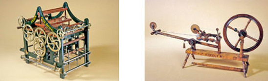
This sampling of patent models from the Textile Collection describes the two major groupings, textile machinery and sewing machines. In both groups, the examination of the models begins with the earliest of the inventions. In this early group of patent models, the textile machinery models date from 1837 to 1840, and the sewing machine models from 1842 to 1854.

For more information about the Museum’s patent model collection, see Patent Model Index, Guide to the Collections of the National Museum of American History.

Sewing Machine Patent Model . Patent No. 6439, issued May 8, 1849John Bachelder of Boston, Massachusetts.John Bachelder of Boston, Massachusetts, submitted this sewing machine patent model for his Patent No. 6439, which was granted on May 8, 1849.
Description
Sewing Machine Patent Model . Patent No. 6439, issued May 8, 1849
John Bachelder of Boston, Massachusetts.
John Bachelder of Boston, Massachusetts, submitted this sewing machine patent model for his Patent No. 6439, which was granted on May 8, 1849. Bachelder’s machine sewed with a chain-stitch. He did not claim this chain-stitch mechanism as it was patented earlier in February in 1849 by Charles Morey and Joseph B. Johnson of Massachusetts. Instead he focused on improving the cloth feed. On this model, Bachelder used a wide continuous leather belt inserted with sharp pins to hold the cloth and enable the leather belt to move the cloth forward as it was being sewn. After being stitched, the fabric would be disengaged from the points by a curved piece of metal. This was the first patent for a continuous sewing, intermittent feeding mechanism.
Although Bachelder did not manufacture his sewing machine, his patent and later reissues of it were bought by I. M. Singer, and became one of the central patents to form the Sewing Machine Combination in 1856. This organization consisted of three sewing machine manufacturers, I. M. Singer Co., Wheeler & Wilson Co., and the Grover & Baker Co., and the inventor, Elias Howe Jr., who all agreed to pool their important patents and stop patent litigations between them. This allowed them to move ahead with manufacturing and marketing of their own sewing machine and collect license fees from other companies wanting to use their patents.
Location
Currently not on view
model constructed
before 1849-05-08
patent date
1849-05-08
inventor
Bachelder, John
ID Number
TE.T06051
catalog number
T06051.000
patent number
006439
accession number
89797
Sewing Machine Patent Model. Patent No. 2,466, issued February 21, 1842John James Greenough of Washington, D.C.In 1842, John Greenough received the first American patent for a sewing machine. Greenough’s patent model used a needle with two points and an eye in the middle.
Description
Sewing Machine Patent Model. Patent No. 2,466, issued February 21, 1842
John James Greenough of Washington, D.C.
In 1842, John Greenough received the first American patent for a sewing machine. Greenough’s patent model used a needle with two points and an eye in the middle. To make a stitch, the needle would completely pass through the material by means of a pair of pinchers on either side of the seam. The pinchers traveled on a rack and opened and closed automatically. The needle was threaded with a length of thread, and required constant rethreading.
This type of sewing was classified as a short-thread machine. The machine was designed for sewing leather, and an awl preceded the needle to pierce a hole. The leather was held between clamps on a rack that could be moved, to produce a back stitch, or forward to make a shoemaker’s stitch. The material was fed automatically at a selected rate, according to the length of stitch desired. A weight drew out the thread, and a stop-motion shut down the machinery when a thread broke or became too short. Feed was continuous for the length of the rack-bar, and then it had to be set back. The turn of a crank set all motions to work. Greenough did not commercially manufacture his invention and his patent model remains as the only evidence.
He held several profitable patents for shoe-pegging machinery. He had many interests and his other patents included ones for plate glass; lampshades; looms; firearms; meters; propellers; gearing; hinges; power-transmitters; car steps; and a paper bag-making machine.
Greenough worked at the Patent Office from 1837 to 1841, supervising draftsmen who were restoring the patent drawings lost in the disastrous 1836 fire. Later he became an attorney working mostly on patent cases, and established a patent agency in New York City. In 1853, he was one of the founders of the American Polytechnic Journal, which published engravings of recent patents.
Location
Currently not on view
model constructed
before 1842-02-21
patent date
1842-02-21
inventor
Greenough, John J.
ID Number
TE.T06048
catalog number
T06048.000
patent number
002466
accession number
48865
Sewing Machine Patent Model. Patent No. 2,982 issued March 4, 1843.Benjamin W. Bean of New York, New YorkThe second American patent (Patent No. 2,982) for a sewing machine was granted to Benjamin W. Bean on March 4, 1843.
Description
Sewing Machine Patent Model. Patent No. 2,982 issued March 4, 1843.
Benjamin W. Bean of New York, New York
The second American patent (Patent No. 2,982) for a sewing machine was granted to Benjamin W. Bean on March 4, 1843. Bean’s machine made a running stitch by feeding the fabric between the teeth of a series of gears and onto a threaded bent needle. Turning the crank-handle from left to right moves the gearing in a similar motion to a crimping machine. The stationary crooked needle lays in a groove in the gears, with a point at one end and an eye at the other. A wooden screw clamp secures the machine to the worktable.
This invention was similar to Greenough’s in making a running stitch, but the approach was different. Bean’s method, like Greenough’s, was yet another attempt to emulate hand sewing. Although Bean’s running stitch machine had little commercial success, small inexpensive machines were later sold in the 1860s for household use based on this principle. It remained for Elias Howe, three years later, to patent a sewing machine using a lockstitch that functioned differently from the movements of hand sewing.
Location
Currently not on view
model constructed
before 1843-03-04
patent date
1843-03-04
inventor
Bean, Benjamin W.
ID Number
TE.T06049
catalog number
T06049.000
patent number
002982
accession number
48865
Sewing Machine Patent Model. Patent No. 7776, issued November 12, 1850. Allen Benjamin Wilson of Pittsfield, Massachusetts.Allen B. Wilson was one of the most creative and innovative of the early inventors.
Description
Sewing Machine Patent Model. Patent No. 7776, issued November 12, 1850. Allen Benjamin Wilson of Pittsfield, Massachusetts.
Allen B. Wilson was one of the most creative and innovative of the early inventors. Born in Willett, New York, in 1823, he was apprenticed at age sixteen as a cabinetmaker. Later in 1847, he moved to Adrian, Michigan, and worked as a journeyman cabinetmaker. It was here, far removed from New England and the efforts by other inventors, that he began to design a different sewing machine. After recovering from an illness, he moved back east to Pittsfield, Massachusetts, and began to perfect his new concept for a sewing machine.
In 1850, Wilson developed a prototype for a reciprocating-shuttle machine. When the needle went through the cloth, it formed a loop below the seam. A shuttle that was pointed on both ends held a second thread that was passed through the loop and as the tension on the thread was tightened, a lockstitch was made. This shuttle could be moved both forward and backwards to form a stitch on both movements, unlike the shuttles of Hunt and Howe, which only created a stitch in one direction.
Based on these same ideas, he made a second machine that he submitted to the U.S. Patent Office and was granted Patent No. 7,776 on November 12, 1850. Presumably, Wilson’s skills as a cabinetmaker came into use with this model as it is almost entirely made out of wood and painted black to look like metal. Constructing a model out of wood, rather than metal, was a less expensive and easier way to build, requiring fewer specialized tools. On the underside of the metal raceway is stamped “Deall & Sons,” evidence that Wilson used a machinist to fabricate this part.
Fortunately, Wilson met Nathaniel Wheeler, partner of the firm of Warren and Woodruff of Watertown, Connecticut. He moved to Watertown to join in the partnership and to continue to perfect his sewing machine.
In his second patent (Patent No. 8,296, issued August 12, 1851) Wilson developed the rotary hook and bobbin to replace the shuttle mechanism in his first patent (Patent No. 7776, issued November 12, 1850.) The rotary hook opened the loop of the needle thread, while a reciprocating bobbin carried the second thread through the loop to complete the lockstitch.
In order to avoid patent litigation that the reciprocating bobbin might have caused, Wilson developed his third unique invention, the stationary bobbin (Patent No. 9,041, issued June 15, 1852.) In Wilson’s rotary hook and stationary bobbin, the lockstitch was made by locking the needle thread with the bobbin thread by passing the needle thread loop under the bobbin. The driving shaft carried the circular rotary hook, which resulted in a revolutionary method of sewing.
For his patent model, Wilson submitted a commercial Wheeler and Wilson sewing machine that had been manufactured the previous year. The evolution of his ideas from the simple wooden model to the successful manufactured machine beautifully illustrates the progress of his novel inventions.
In 1853 the Wheeler and Wilson Manufacturing Company was organized to manufacture sewing machines based on Allen Wilson patents. In 1856, the company moved to Bridgeport, Connecticut, and became the largest and most successful manufacturer of sewing machines in the 1850s and 1860s.
Location
Currently not on view
model constructed
before 1850-11-12
patent date
1850-11-12
patentee
Wilson, Allen B.
inventor
Wilson, Allen B.
ID Number
TE.T06052
catalog number
T06052.000
accession number
48865
patent number
007776
Sewing Machine Patent ModelPatent No. 3,389, issued December 27, 1843George Henry Corliss of Greenwich, New YorkIn 1825, George Corliss’s physician father moved the family to Greenwich, New York, where George, then 8, grew up.
Description
Sewing Machine Patent Model
Patent No. 3,389, issued December 27, 1843
George Henry Corliss of Greenwich, New York
In 1825, George Corliss’s physician father moved the family to Greenwich, New York, where George, then 8, grew up. The son spent several years as a young man clerking in a country store and in 1838 opened his own country store in Greenwich. While running the store, George received complaints about the stitching of leather boots from a customer. Since all stitching was done by hand, George wondered why a machine had not been invented that would stitch stronger seams.
He analyzed the saddler’s stitch, which was commonly used to stitch boot seams, and developed the concepts of the mechanisms that would be necessary to reproduce the stitch with a machine. By 1843, he had developed such a machine and received Patent Number 3,389. In his patent specification, he described the operation of the “Sewing Engine” as follows: “Like the common process of sewing by hand, it is provided in this machine that the article under operation be perforated for each stitch, and that the perforation be filled with a thread passed through it from each side. The instruments by which this is affected repeat their operations always at the same point. The article to be sewed is therefore moved at each stitch.” Knight’s Mechanical Dictionary of 1881 indicated that the machine was similar in operation to the Greenough patented in 1842 in the use of the running stitch. In his patent claims, Corliss noted the rectilinear and lateral movements of the awls; the movements of the needles; the combination of levers; the method of forming stitches; and the mechanism that prevents the entanglement of threads.
Hoping to promote his sewing machine patent, George moved his family to Providence, Rhode Island, in 1844 to gain financial backing and machine shop experience. Associating himself in business with John Barstow and Edwin J. Nightingale to develop and manufacture steam engines, Corliss received many patents relating to steam engines and their associated components. His interest in sewing machines was overtaken by his pursuit of improvements to steam engines, for which he became famous.
Location
Currently not on view
model constructed
before 1843-12-27
patent date
1843-12-27
inventor
Corliss, George H.
ID Number
TE.T06110
catalog number
T06110.000
patent number
003389
accession number
89797
Doubling and Twisting Thread Machine Patent ModelPatent No. 352, issued August 15, 1837John Golding, Dedham, MassachusettsIn his patent specification, Golding noted that the frame of the doubling and twisting machine was to be constructed like any of the “modern” frames.
Description
Doubling and Twisting Thread Machine Patent Model
Patent No. 352, issued August 15, 1837
John Golding, Dedham, Massachusetts
In his patent specification, Golding noted that the frame of the doubling and twisting machine was to be constructed like any of the “modern” frames. It would have gears, and an eccentric, or heart, motion to guide the thread on the spool. His patent claim concerned the arrangement of the machinery that prevented wasting the thread if it broke. This was accomplished by stopping the spindle and raising the feeding-down roller.
Location
Currently on loan
model constructed
before 1837-08-15
patent date
1837-08-15
inventor
Golding, John
ID Number
TE.T11416.064
catalog number
T11416.064
accession number
89797
patent number
352
Cloth Napping Machine Patent ModelPatent No. 350, issued August 8, 1837Benjamin Swasey of Mount Vernon, MaineSwasey’s patent concerned the setting of teazles ( thistle-like plant heads) in the wires of the large napping cylinder.
Description
Cloth Napping Machine Patent Model
Patent No. 350, issued August 8, 1837
Benjamin Swasey of Mount Vernon, Maine
Swasey’s patent concerned the setting of teazles ( thistle-like plant heads) in the wires of the large napping cylinder. He also claimed certain springs and levers that shifted the cloth rollers in and out of gear. This shifting of the cloth rollers caused the cloth to come in contact with the teazles as the cloth was wound forward and then disengaged the cloth from the teazles as the cloth rewound.
In this way, the cloth could roll from one cylinder to another as long as necessary to ensure a well-napped surface. Also, the shifting of gears did not require a person to match and unmatch the gears. Friction bands on the ends of the cloth rollers, together with hanging weights, kept tension on the cloth even.
Location
Currently not on view
model constructed
before 1837-08-08
date made
before1837-08-08
patent date
1837-08-08
inventor
Swasey, Benjamin
ID Number
TE.T11403.011
accession number
89797
catalog number
T11403.011
accession number
89797
patent number
350
Cordage Machine Patent ModelPatent No.
Description
Cordage Machine Patent Model
Patent No. 596, issued February 7, 1838
Moses Day of Roxbury, Massachusetts
This patent was an improvement on Day’s earlier patent (9692x) of June 2, 1836, which was destroyed in the 1836 fire and reconstructed by the Patent Office for the Columbian Exposition of 1893.
The difference between the two patents is the addition of a gauge-plate to the end of the machine, by which it became a strandmaker. Day stated that his method of making cordage had two advantages over those in common use. First, the twist given to the strand was uniform throughout its length. Second, as the cord was made, it was wound on a bobbin, thereby eliminating the need for long rope walks and large buildings. The whole process could be done in a room that was only slightly larger than the cordage machine and the bobbin frame.
Location
Currently not on view
model constructed
before 1838-02-07
patent date
1838-02-07
inventor
Day, Moses
ID Number
TE.T11405.045
accession number
89797
catalog number
T11405.045
patent number
596
Self-Adjusting Loom Temple Patent ModelPatent No. 291, issued July 22, 1837Samuel P. Mason of Newport, Rhode IslandTemples are attachments on looms designed to keep the cloth at a uniform width during weaving.
Description
Self-Adjusting Loom Temple Patent Model
Patent No. 291, issued July 22, 1837
Samuel P. Mason of Newport, Rhode Island
Temples are attachments on looms designed to keep the cloth at a uniform width during weaving. Self-acting temples required no adjustment as the cloth was woven, for they automatically adjusted their position. The greater speed obtained with power weaving made the use of self-acting temples a necessity.
The basic construction of Mason’s temples was similar to others of the period. The patented feature of his temple concerned the arrangement of the parts by which the jaws or forceps were forced open and released their hold on the cloth.
Mason patented other useful textile machinery. Notable were an 1830 speeder for roving cotton (a speeder is a machine used in cotton yarn spinning that inserts a twist to the yarn and winds it on the bobbin) and a cotton whipper (a machine that separates clumps of cotton) in 1834. James Montgomery, in his 1840 edition of “Cotton manufacture of the United States Contrasted with that of Great Britain,” wrote that he considered the whipper the best, cheapest, and simplest that he had seen in factory use over a span of thirty years.
Location
Currently not on view
model constructed
before 1837-07-22
patent date
1837-07-22
inventor
Mason, Samuel P.
ID Number
TE.T11414.073
patent number
291
catalog number
T11414.073
patent number
001838
accession number
89797
Loom Heddles and Harness Patent ModelPatent No. 544, issued December 29, 1837Benjamin Hartford and William B.
Description
Loom Heddles and Harness Patent Model
Patent No. 544, issued December 29, 1837
Benjamin Hartford and William B. Tilton of Enfield, New Hampshire
Hartford and Tilton improved upon the construction of heddles (the mechanisms that raise and lower warp threads) by using strips of rolled flat metal with an eye punched through the middle of each strip to allow for the passage of warp yarns. Heddles were commonly constructed of cord. The replacement of metal for cord produced a more durable heddle. These one-piece metallic strips and the construction of the heddle frame were the basis of their patent. The heddles slid on two rods and were attached to adjustable clasps, permitting the heddles to correspond to the part of the reed (a comb-like device used to space the warp yarns evenly) that was in operation.
Location
Currently not on view
model constructed
before 1837-12-29
patent date
1837-12-29
inventor
Hartford, Benjamin
Tilton, William B.
ID Number
TE.T11409.015
patent number
544
accession number
89797
catalog number
T.11409.15
Sewing Machine Patent ModelPatent No. 7,824, issued December 10, 1850Frederick R. Robinson of Boston, MassachusettsIn his Annual Report to the Congress of Patents for 1850, Commissioner Thomas Ewbank stated that 995 patents were issued. One of those patents was to Frederick R.
Description
Sewing Machine Patent Model
Patent No. 7,824, issued December 10, 1850
Frederick R. Robinson of Boston, Massachusetts
In his Annual Report to the Congress of Patents for 1850, Commissioner Thomas Ewbank stated that 995 patents were issued. One of those patents was to Frederick R. Robinson for improvements to sewing machines. Robinson’s patent was used commercially by the firm of Howard & Davis of Boston to manufacture sewing machines. In addition to using Robinson’s patent, the machines they built utilized improvements patented by Sylvester H. Roper of Worcester, Massachusetts (Patent No. 11,521 issued on August 15, 1854) and with additional improvements (Patent No. 16,026 issued on November 4, 1856). Howard & Davis were best known for their manufacture of high-grade clocks and watches, although they also built fire engines and precision balances.
As Robinson stated, “The object of my invention is to produce either what is generally termed ‘stitch and back stitch’ sewing, or ordinary stitching.” He notes that this is frequently called the running stitch or basting stitch. His specific patent claim was “The combination of two needles, two thread-guides, and a cloth-holder made to operate together . . . and . . . the improvement of making the needles with springs and applying mouth-pieces or pressers to them, and on each side of the flange of the base-plate . . .”
Scientific American, November 1, 1856, describes the machine based on the patents mentioned above as: “Robinson & Roper exhibit their new improved sewing machines, which appear to operate with great success. Two needles are employed, the points of which are furnished with hooks that alternately catch the thread and form the stitch. The finest kind of cotton thread or silk can be used.”
Location
Currently not on view
model constructed
before 1850-12-10
patent date
1850-12-10
inventor
Robinson, Frederick R.
ID Number
TE.T06111
catalog number
T.6111
accession number
89797
patent number
7824
Carpet Patent ModelPatent No. 1,028, issued December 10, 1838John Humphries of New York, New YorkHumphries’s innovation was the addition of a supplementary layer to the bottom of a carpet to provide an extra cushion and to strengthen the overall structure.
Description
Carpet Patent Model
Patent No. 1,028, issued December 10, 1838
John Humphries of New York, New York
Humphries’s innovation was the addition of a supplementary layer to the bottom of a carpet to provide an extra cushion and to strengthen the overall structure. The added stuffer weft is a stout, loosely twisted cord, woven into the underside of the carpet and interlaced with the ground warp. These samples of carpeting are important because they are the earliest known examples of patented carpeting in the United States.
Whether this patent was utilized is unknown but there is evidence of Humphries being involved in the manufacture of carpeting. The Journal of the Franklin Institute lists premiums awarded at their eighth exhibition in 1833. John Humphries was presented a premium for four pieces of Brussels carpeting. The judges noted that “these goods are of excellent quality and style, and satisfactory assurances have been received that they are exclusively of American workmanship throughout all the processes from the raw material to the finished product of the loom.”
Location
Currently not on view
model constructed
before 1838-12-10
patent date
1838-12-10
inventor
Humphries, John
ID Number
TE.T18362
catalog number
T18362.000
patent number
001028
accession number
1978.2402
Spinning Wheel Patent ModelPatent No. 710, issued April 25, 1838Hiram F. Wheeler of Springville, PennsylvaniaHiram Wheeler’s domestic wheel was for spinning wool.
Description
Spinning Wheel Patent Model
Patent No. 710, issued April 25, 1838
Hiram F. Wheeler of Springville, Pennsylvania
Hiram Wheeler’s domestic wheel was for spinning wool. He titled his invention “inclined spinner,” referring to the fact that the operator would sit at the wheel as opposed to standing and walking when using the typical wool wheel. When the treadle was forced down by the operator’s foot, a cord pulled the carriage and spinning wheel head away from the spinner. A weight brought both of them back toward the spinner. This movement of the carriage was equivalent to the spinner walking forward to the spindle tip for the draw out and then back to the wheel. Wheeler specifically claimed as his invention this sliding action of the wheel head.
Location
Currently not on view
model constructed
before 1838-04-25
patent date
1838-04-25
inventor
Wheeler, Hiram F.
ID Number
TE.T11407.001
catalog number
T11407.001
accession number
89797
patent number
710
Spindle and Flyer Patent ModelPatent No. 781, issued June 12, 1838Richard E.
Description
Spindle and Flyer Patent Model
Patent No. 781, issued June 12, 1838
Richard E. Yerkes of Philadelphia, Pennsylvania
According to his patent specification, Yerkes patented “the revolving arrangement and combination of the sliding shaft, with the broach, or with the spool, for the purpose of removing and renewing the latter . . . .” The action of the sliding shaft enabled the operator to remove and change the spool when the spring was pressed down. In addition, he patented the ring in combination with the flyers that distributed the yarn on the spool. Yerkes intended his improvements to be used on machines for spinning cotton and other fibers.
Location
Currently not on view
model constructed
before 1838-06-12
patent date
1838-06-12
inventor
Yerkes, Richard E.
ID Number
TE.T11420.080
catalog number
T11420.080
accession number
89797
patent number
781
Sewing Machine Patent Model. Patent No. 4,750, issued September 10, 1846. Elias Howe Jr. of Cambridge, Massachusetts.While working as a journeyman machinist, Elias Howe Jr. wrestled for years to find a way to mechanize sewing.
Description
Sewing Machine Patent Model. Patent No. 4,750, issued September 10, 1846. Elias Howe Jr. of Cambridge, Massachusetts.
While working as a journeyman machinist, Elias Howe Jr. wrestled for years to find a way to mechanize sewing. With the family pinched by poverty, his wife sewed for others by hand at home. Watching her sew, Howe visualized ways to mechanize the process. In 1845, he built his first sewing machine and soon constructed an improved model, which he carried to the Patent Office in Washington to apply for a patent. He received the fifth United States patent (No. 4,750) for a sewing machine in 1846.
Howe’s model used a grooved and curved eye-pointed needle carried by a vibrating arm. The needle was provided with thread from a spool. Loops of thread from the needle were locked by a second thread carried by a shuttle, which moved through the loop by means of reciprocating drivers.
The cloth hung vertically, impaled on pins on a metal baster plate. The baster plate moved intermittently under the needle by means of a toothed wheel. The length of each stitching operation depended upon the length of the baster plate, and only straight seams could be sewn. When the end of the baster plate reached the position of the needle, the sewing was stopped. The cloth was removed from the baster plate, and the plate was moved back to its original position. The cloth was repositioned on the pins and the process was repeated until the sewing was finished. This resulted in an imperfect way to sew, but it marked the beginning of successful mechanized sewing.
Howe’s patent claims were upheld in court to allow his claim to control the combination of the eye-pointed needle with a shuttle to form a lockstitch. Howe met with limited success in marketing his sewing machine. Subsequent inventors patented their versions of sewing machines, some of which infringed on Howe’s patent. He quickly realized his fortune depended on defending his patent and collecting royalty fees from sewing machine manufacturers. These royalty licenses granted companies the right to use the Howe patent on their machines.
In 1856, after years of lawsuits over patent rights, Elias Howe and three companies, Wheeler & Wilson, Grover and Baker, and I. M. Singer, formed the first patent pool in American industry. The organization was called the Sewing Machine Combination and/or the Sewing Machine Trust. This freed the companies from expensive and time-consuming litigation and enabled them to concentrate on manufacturing and marketing their machines.
Location
Currently not on view
model constructed
before 1846-09-10
patent date
1846-09-10
inventor
Howe, Jr., Elias
model maker
Howe, Jr., Elias
ID Number
TE.T06050
catalog number
T.6050
patent number
004750
accession number
48865
Hand Card Patent ModelPatent No. 863, issued August 1, 1838George Faber of Canton, OhioFaber’s patent related to the construction of the common hand card used for carding cotton or wool prior to the spinning process.
Description
Hand Card Patent Model
Patent No. 863, issued August 1, 1838
George Faber of Canton, Ohio
Faber’s patent related to the construction of the common hand card used for carding cotton or wool prior to the spinning process. He specifically patented using wood veneer, instead of leather, for the foundation that contained the card’s wire teeth. The wood was cut from 1/8 to 3/16 of an inch in thickness, 4 inches in width, and 4 to 8 inches in length. The wood was then steeped in water to soften it so that when placed in a card-making machine, it could be pricked and the teeth inserted. The veneer was nailed to another piece of wood and a handle inserted to form the hand card.
Although Faber did not claim credit for inventing the card-making machine, in his patent specification he did mention that he had made improvements on it.
Location
Currently not on view
model constructed
before 1838-08-01
patent date
1838-08-01
inventor
Faber, George
ID Number
TE.T11396.030
catalog number
T11396.030
accession number
89797
patent number
863
Spinning, Doubling, and Twisting Silk Machine Patent ModelPatent No. 977, issued on October 10, 1838Harrison Holland of Northampton, MassachusettsThe central part of Holland’s patent concerned the stop motion mechanism on a silk thread making machine.
Description
Spinning, Doubling, and Twisting Silk Machine Patent Model
Patent No. 977, issued on October 10, 1838
Harrison Holland of Northampton, Massachusetts
The central part of Holland’s patent concerned the stop motion mechanism on a silk thread making machine. If a thread broke, a small rod, connected to each of the threads by bent wires, would drop. A lever, to which the rod was attached, would come in contact with the drum and then stop the machine by throwing it out of gear. Also included in the patent was a method to change the twist of the silk thread by using a short cylinder.
Location
Currently not on view
model constructed
before 1838-10-10
patent date
1838-10-10
inventor
Holland, Harrison
ID Number
TE.T11407.027
accession number
89797
patent number
977
catalog number
T11407.027

Our collection database is a work in progress. We may update this record based on further research and review. Learn more about our approach to sharing our collection online.

If you would like to know how you can use content on this page, see the Smithsonian's Terms of Use. If you need to request an image for publication or other use, please visit Rights and Reproductions.