Other Calculating Machines

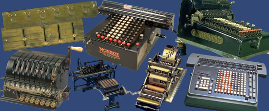
Several mechanisms other than stepped drums or pinwheels were used in calculating machines, both in early prototypes and in successful products.

This experimental model is one of the first, if not the first , calculating machine built in the United States. It was made by Frederick Parsons Warren (1839-1875) of Three Oaks, Michigan, in 1872.The metal machine has a row of 11 result dials that slide along the back.
Description
This experimental model is one of the first, if not the first , calculating machine built in the United States. It was made by Frederick Parsons Warren (1839-1875) of Three Oaks, Michigan, in 1872.
The metal machine has a row of 11 result dials that slide along the back. Each dial has a strip of paper numbered from 0 to 9 twice around the rim. Between the dials are spiral gears, which were to be part of the carry mechanism. In front of the dials and gears is a row of seven gear segments. In front of and linked to these are seven additional gear segments. A lever that extends to the front of the machine can be placed in any tooth of one of these forward segments. At the top of the machine is a tilted disc that has four toggles protruding from it.
There are no maker’s marks.
Compare MA.311938 and MA.311939.
According to L. Leland Locke, Warren was a teacher, itinerant photographer, and then watchmaker by trade. His invention was inspired by his reading about Charles Babbage’s difference engine in 1864. He designed his machines to demonstrate what might be done with machinery, not for sale.
Reference:
L. Leland Locke, “The Warren Calculating Engine,” Business Equipment Topics, October, 1931, vol. 79, p. 8, 9. 48, 49.
Location
Currently not on view
date made
1872
ID Number
MA.311938
catalog number
311938
accession number
155183
This is the second version of Warren’s calculating machine. Across the front is a brass rod with ten large teeth, one shorter one, and a hollow brass cylinder. Between the teeth are ten levers that link to toothed segments at the back of the machine.
Description
This is the second version of Warren’s calculating machine. Across the front is a brass rod with ten large teeth, one shorter one, and a hollow brass cylinder. Between the teeth are ten levers that link to toothed segments at the back of the machine. The front and back are open; the sides are of a ferrous metal painted black. At the top is a hollow brass rod, mounted across the machine, which has two brass circular structures on it. This is used as a plunger to activate the mechanism. Brass rods with large teeth extend from both sides of the back. There also is a ferrous piece in the shape of a large comb that is attached to the top back of the piece. The machine appears incomplete.
There are no maker’s marks.
Compare MA.311938 and MA.311939.
According to L. Leland Locke, Warren was a teacher, itinerant photographer and then watchmaker by trade. His invention was inspired by his reading about Charles Babbage’s difference engine in 1864. He designed his machines to demonstrate what might be done with machinery, not for sale. A more complete form of the machine, which was exhibited after Warren’s death, is now in the collections of the Michigan State University Museum.
References:
L. Leland Locke, “The Warren Calculating Engine,” Business Equipment Topics, October, 1931, vol. 79, pp. 8, 9. 48, 49.
"Home and Foreign Gossip," Harper’s Weekly, May 22, 1875, vol. 19 #960, p. 423.
Location
Currently not on view
date made
1874
ID Number
MA.311939
catalog number
311939
accession number
155183
This rough model of a calculating machine that would multiply a number by a digit directly and print the result was submitted to the U.S. Patent Office by Edmund D. Barbour in 1872. It has a rectangular wooden base with nine grooves in it.
Description
This rough model of a calculating machine that would multiply a number by a digit directly and print the result was submitted to the U.S. Patent Office by Edmund D. Barbour in 1872. It has a rectangular wooden base with nine grooves in it. The rightmost groove contains a rectangular brass plate with nine rows of teeth in it. The first row has one tooth, the second, two, and so forth. This plate has a metal handle, marked with the digits from 1 to 9, that can be pulled forward to enter a digit. It is a modification of the cylinder in Barbour’s patent 130404 (see MA.309172 ). A complete machine would have nine such plates.
To the right of the grooved wooden base and its metal plate is another brass plate on which is mounted a mechanism for controlling a slide that is supposed to move over the rectangular plate, carrying out desired arithmetic operations. In this machine, multiplication is carried out by repeated motion of the slide, rather than in a single motion as in Barbour’s earlier invention. Two rotating sets of brass gears, each equipped with a type wheel, are intended to demonstrate how the results of calculations might be printed automatically. The object has no maker’s marks. No successful product emerged directly from Barbour’s patents.
Compare MA.309172, MA.309173, and MA.318168.
The Edmund D. Barbour who took out this patent was probably Edmund Dana Barbour (1841–1925), a Boston native who reportedly gained a fortune in the China trade before returning to Boston in 1871, not long before taking out this patent. Barbour took our two other patents calculating machines, invested successfully in the Bell Telephone Company, carried out extensive genealogical research, and left most of his fortune in bequests to Harvard University, the Massachusetts Institute of Technology and Radcliffe College.
References:
Edmund D. Barbour, "Improvement in Calculating Machines," U.S. Patent 133188, November 19, 1872.
J.A.V. Turck, Origin of Modern Calculating Machines, Chicago: Western Society of Engineers, 1921, pp. 180–187.
“Sharon’s Rich Men,” Boston Daily Globe, February 20, 1888, p. 6.
“Fund for Three Local Colleges: Edmund D Barbour’s Will Gives Each $20,000 a Year,” Boston Daily Globe, March 13, 1925.
J. Gardner Bartlett, “Edmund Dana Barbour,” The New England Historical and Genealogical Register , vol. 79, October 1925, pp. 339–344.
Location
Currently not on view
date made
1872
patentee
Barbour, Edmund D.
maker
Barbour, Edmund D.
ID Number
MA.309173
accession number
89797
catalog number
309173
This small brass U.S. Patent Office model of a calculating machine is a modification of Edmund D. Barbour’s two earlier machines. It has a rectangular base on which is mounted crosswise a rotating cylinder.
Description
This small brass U.S. Patent Office model of a calculating machine is a modification of Edmund D. Barbour’s two earlier machines. It has a rectangular base on which is mounted crosswise a rotating cylinder. The cylinder has nine crosswise grooves that fill somewhat less than a quarter of the surface. Metal bands separate the grooves into columns, and each column has a set of nine sliding markers that fit in the grooves. Sliding these markers sets a number. There also is an array of pins around the cylinder, which is used in carrying. There are gears on both sides of the cylinder.
The registering mechanism has an open frame that holds three rods. One rod holds four type wheels, and the other two rods hold four gears each. Each type wheel has the numbers from 0 to 9.
The machine has no maker’s marks.
Compare 309172, 309173, and 318168.
The Edmund D. Barbour who took out this patent was probably Edmund Dana Barbour (1841–1925), a Boston native. He reportedly gained a fortune in the China trade, returning to Boston in 1871. Barbour took out two other patents for calculating machines; invested successfully in the Bell Telephone Company; carried out extensive genealogical research; and left most of his fortune in bequests to Harvard University, the Massachusetts Institute of Technology, and Radcliffe College. The model apparently did not lead to a successful product.
References:
U.S. Patent 168080, September 28, 1875.
J. A. V. Turck, Origin of Modern Calculating Machines, Chicago: Western Society of Engineers, 1921, pp. 180–187.
“Sharon’s Rich Men,” Boston Daily Globe, February 20, 1888, p. 6.
“Fund for Three Local Colleges: Edmund D Barbour’s Will Gives Each $20,000 a Year,” Boston Daily Globe, March 13, 1925.
Kwang-Ching Liu, Anglo-American Steamship Rivalry in China, Cambridge: Harvard University Press, 1962, esp. pp. 92–98, 128.
J. Gardner Bartlett, “Edmund Dana Barbour,” The New England Historical and Genealogical Register , vol. 79, October, 1925, pp. 339–344. This obituary does not mention any inventive activity of Barbour.
Location
Currently not on view
date made
1875
patentee
Barbour, Edmund D.
maker
Barbour, Edmund D.
ID Number
MA.318168
accession number
155183
catalog number
318168
In 1876 the Massachusetts inventor and entrepreneur George B.
Description
In 1876 the Massachusetts inventor and entrepreneur George B. Grant displayed this calculating machine, as well as a difference engine of his design, at the Centennial Exhibition, a world’s fair held in Philadelphia.
The barrel-type, non-printing machine has a rectangular wooden base, cut out to allow for the motion of a set of wheels that rotates on a shaft near the bottom. This shaft is linked to a larger upper cylinder by gears so that the wheels and the cylinder turn simultaneously when a handle at the right end of the upper cylinder is rotated. The frame for the instrument consists of hollow discs at opposite ends of the base, which are connected to the two shafts already mentioned, and a third shaft which carries a set of 20 spring claws that link to the gears of the wheels.
Part of the upper cylinder has a metal collar that can be set at any of 18 positions on the cylinder with a locking pin. This collar supports 18 movable rings. Each ring has an adding pin and a stud on it which may be set at any of ten positions, labeled by the digits from 0 to 9. The lower cylinder has 20 recording wheels on it, each provided with 30 teeth. The digits from 0 to 9 are stamped three times around each wheel. The spring claws fit the gears of the recording wheels. If a claw is pushed down, it engages the gear of the recording wheel, causing it to rotate. Studs on the wheel lead to carrying by engaging the next claw over.
This model has no mechanism for displaying the multiplier or multiplicand. A flat disk at the end of a lever on the left side serves as a brake on the operating wheels, indicating when the operating crank has been turned through one revolution.
For a related, later U S. patent model, see MA.311940.
The judges at the Centennial Exhibition gave Grant an award for his invention, and described his machine as “superior to all other instruments of its class yet produced.” It was lauded by actuaries and distinguished professors, but never gained large sales. This version of the machine sold for $100.
References:
George B. Grant, “Improvement in Calculating Machines,” U.S. Patent 138245 (April 29, 1873).
George B. Grant, “On a New Difference Engine,” American Journal of Science, ser. 3, vol. 1 (August 1871), pp. 113–118.
George B. Grant, “A New Calculating Machine,” American Journal of Science, ser. 3, vol. 8 (1874), pp. 277–284.
L. Leland Locke, “George Barnard Grant,” Dictionary of American Biography, vol. 7, New York: Scribners, 1931, pp. 487–488.
Robert K. Otnes, “Calculators by George B. Grant,” Historische Buerowelt, no. 19, October 1987, pp. 15–17.
Accession files 118852 and 155183.
George B. Grant, “The Calculating Machine,” Boston: Albert J. Wright, Printer, 1878.
Location
Currently not on view
date made
1876
maker
Grant, George B.
ID Number
MA.310645
catalog number
310645
accession number
118852

Our collection database is a work in progress. We may update this record based on further research and review. Learn more about our approach to sharing our collection online.

If you would like to know how you can use content on this page, see the Smithsonian's Terms of Use. If you need to request an image for publication or other use, please visit Rights and Reproductions.