Circle, Ellipse, Parabola, Hyperbola. These are all names familiar to anyone who has had high school analytic geometry. They are the four conic sections, known to the ancient Greeks. The word section means to cut or divide into sections, so conic sections are cuts, or cross sections of a cone. Though they can arise in any cone, traditionally they are considered as coming from a right circular cone (a cone whose axis is perpendicular to its base). The model pictured in figure 1 is of a wooden right circular cone and shows the conics sections as they arise when the cone is cut by a plane.
") |
Fig 1. Conic Section model showing, from top to bottom, and ellipse, a parabola, hyperbola and circle (base of cone). SI image DOR2013-17883 |
A circle is formed when a plane cuts the cone parallel to the base or perpendicular to the axis of the cone. The other three conics are formed when the cutting plane is no longer parallel to the base (or perpendicular to the axis). After the circle, the next conic section encountered in school is the ellipse. The word ellipse comes from the Greek elleipsis and means “to fall short”. An ellipse is formed when the cutting plane meets the base at an angle less than, or falls short of, the angle formed by the base and the side of the cone. In figure 1 above, notice how the angle the section makes with the base, if it were extended, is more shallow than the angle the side of the cone makes with the base. Thus it “falls short”. The cutting plane cuts a complete closed curve which is depicted in the top slice of the model above and in figure 2 below.
 |
Fig 2. One piece of the conic section model showing an ellipse. SI image DOR2013-17886 |
Parabola comes from the Greek parabole and means “comparison”. A parabola is formed when the cutting plane is inclined to the base at the same angle as the side of the cone (middle cut in figure 1). A parabola does not form a closed curve but a U shape. Finally, the word hyperbola comes from the Greek hyperbole which means to “go beyond” and is formed when the plane cuts the cone at an angle greater than the angle at which the side of the cone meets the base (bottom cut in figure 1). Hyperbolas form very open U or corner shapes. Both a parabola and hyperbola are show in the figure 3 below which shows the middle piece of the conic section model of figure 1.
 |
Fig 3. Section of cone showing a parabola on the back side and a hyperbola on the front side. SI image DOR2013-17887 |
The conics were known to the ancient Greeks. Arches and bridges have been constructed using ellipses and parabolas since the Romans. But scientific applications of the conics (other than circles) were not discovered until comparatively recently. For example, Galileo (1683) realized that any projectile follows a parabolic path, while Kepler (1609) discovered that all planets follow elliptical paths around the sun, as opposed to perfect circles as believed since antiquity. In fact, all orbital motion under the influence of gravity can be described using one of the four conic sections based on the mass and speed of the body in orbit. Today, the conics are used to describe the motion of myriads of objects from sub-atomic particles to satellites and whole galaxies.
Ellipsographs (also known as elliptographs) are devices used to draw ellipses. Why would you need to draw an ellipse? These curves arise most often in the areas of architectural and engineering drawing as well as in art and graphic design when drawing in perspective. In fact, German artist Albrecht Dürer, known for is precise perspective drawings, invented a compass to draw ellipses in 1540. When drawing plans or blueprints in perspective, a circle when viewed from an angle appears as an ellipse. Many windows, vaulted ceilings, stairs, bridges and arches are elliptical in design and need to be rendered accurately in technical drawings.
An ellipse is an elongated circle with a center C as well as two foci designated by F. The standard equation for an ellipse in Cartesian coordinates is: ![]()
where a is the length of the semi-major axis and b is the length of the semi-minor.
|
Fig 4. Diagram of an ellipse. |
The standard description of an ellipse is the set of all points whose distance to the two foci is a constant. In the diagram above, the sum of the distances r1 + r2 is the same for any point on the ellipse. The eccentricity (e) of an ellipse is a number between 0 and 1 that indicates how elongated the curve is. The eccentricity is the ratio of the distance from one focus to the center compared to the length of the semi major axis (e=f/a). For a circle, the foci are at the center and so the ratio is zero (e=0/a=0). Thus a circle is a special case of an ellipse where the two foci have come together. The larger e, the more elongated the ellipse is. If you let e equal 1, your ellipse would end up being a line segment, it would have zero width. An infinite number of different ellipses can be formed by changing the separation between the two foci (which changes how long it is) or by changing the distance r1+ r2 (which changes how wide the ellipse is).
The easiest way to draw an ellipse it to take a length of string and tie it to make a loop and place it around two tacks pushed into a piece of paper. With a pencil pull the string taught and start drawing, keeping the sting at the same tension the whole while (figure 5). Since the length of string does not change, the total distance to the two foci remains constant. The curve that results is an ellipse. You can draw a perfect circle by simply using only one pin.
The easiest way to draw an ellipse it to take a length of string and tie it to make a loop and place it around two tacks pushed into a piece of paper. With a pencil pull the string taught and start drawing, keeping the sting at the same tension the whole while (figure 5). Since the length of string does not change, the total distance to the two foci remains constant. The curve that results is an ellipse. You can draw a perfect circle by simply using only one pin.
 |
Fig 5. Image of drawing an ellipse using string and pins by the author. |
There are several mechanical devices that draw an ellipse, but most of them use a method equivalent to this simple string procedure. The simplest ellipsograph used in technical drawing is a template or elliptic curve made of wood or plastic created using a variation on the string method. This type of ellipsograph is static and can only draw one size ellipse but is easy and inexpensive to make. A draftsman may have a set of several sizes of these templates. Item 82.0795.38 is one such elliptic curve and was most likely used in the classroom to draw an ellipse on the chalkboard.
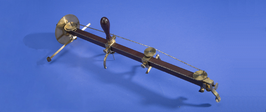
The most common device for drawing ellipses is by using an elliptical compass or elliptical trammel, often referred to as the Trammel of Archimedes. A simple version can be found in handmade toy shops and is often referred to as the “do-nothing machines” or a grinder (fig 5). Animations and directions for building one are readily available on-line.
 |
Fig 6. Trammel of Archimedes. (US Public domain) |
As the handle is turned, the two small wood blocks slide back and forth in their tracks. As one moves away from the center, the other moves toward the center. The sum of the distance of each block to the handle remains constant and is twice the semi-major axis, a. A pencil attached to the end of the handle would trace an ellipse. The vast majority of ellipsographs produced are based on the same theory. However, other than the simple trammel, there are more elaborate ellipsographs that produce more precise drawings. The Smithsonian National Museum of American History has eight ellipsographs in its collections. Apart from the single elliptic curve mentioned above, there are three simple trammels (objects 1985.0112.227, 304722.14, 1987.0379.02) and four high precision items (objects 315255, 308981, 308910, 314861). Three of the items are patent models. All date from the mid-nineteenth century to the mid-twentieth century.
Resources
Gunther, R.T., Handbook of the Museum of the History of Science in the Old Ashmolean Building Oxford, Oxford University Press, Oxford, 1935, p. 66.
Hambly, M., Drawing Instruments 1590-1980, Sotheby’s Publications, 1988, pp. 89-95.
Our collection database is a work in progress. We may update this record based on further research and review. Learn more about our approach to sharing our collection online.
If you would like to know how you can use content on this page, see the Smithsonian's Terms of Use. If you need to request an image for publication or other use, please visit Rights and Reproductions.